
- All
- Product Name
- Product Keyword
- Product Model
- Product Summary
- Product Description
- Multi Field Search


Views: 0 Author: Site Editor Publish Time: 2026-09-28 Origin: Site


Traditional 2-axis and 3-axis turning centers handle simple shafts and pins perfectly. You program the X and Z axes for the profile, and maybe use the C-axis to drill a bolt hole circle on the face. But part geometries rarely stay simple. When prints call for true off-center milling, multi-face operations, or perpendicular cross-holes, a standard lathe hits a hard limit. You are forced to pull the part, move it to a vertical mill, and set it up again. Relying on secondary milling operations inflates work-in-progress inventory. It drives up fixture costs. Every time you unchuck a part and move it, you introduce stack-up tolerance errors across multiple setups. You lose your original datum. A Y-Axis NC Turret bridges the gap between standard turning and high-end mill-turn centers. This guide evaluates the mechanics, tooling requirements, and production variables to help you determine if adding a Y-axis justifies the capital expenditure.
True Off-Center Capability: A Y-axis allows for perpendicular machining off the spindle centerline, eliminating the dimensional inaccuracies associated with polar coordinate interpolation (C-axis).
Single-Setup ROI: Consolidating turning and 3-axis milling operations reduces handling time, scrap rates, and fixture dependencies.
Rigidity and Precision Limits: While highly flexible, a Y-axis turret cannot match the heavy material removal rates or extreme precision of a dedicated multi-axis mill-turn spindle, particularly in tough alloys.
Tooling Dependency: The effectiveness of Y-axis milling is heavily dictated by the turret interface; rigid setups like a BMT tool turret are required to maximize the powered tool turret's potential.
Adding a Y-axis changes the fundamental kinematics of a lathe. On a standard machine, the turret moves in X (toward the centerline) and Z (along the bed). To introduce vertical motion, machine builders alter the carriage design. They typically use a wedge design or a secondary slide mechanism. This mechanical addition allows the entire turret assembly to move orthogonally relative to the X and Z axes. The tool can physically rise above or drop below the main spindle centerline.
Let us look at the wedge design first. The wedge interpolates the X and Y axes simultaneously to achieve true vertical motion. It maintains a lower center of gravity. This keeps the cutting forces closer to the base casting, which helps dampen vibration during heavy roughing. The secondary slide design stacks a Y-axis way system directly on top of the X-axis. It offers straightforward programming kinematics but introduces a slightly taller profile. Both methods give the operator the ability to position an endmill or drill perfectly off-center.
This physical movement is vastly different from using an interpolated C-axis. Many machinists try to fake a Y-axis by combining X-axis feed with C-axis rotation. This is called polar coordinate interpolation. It works fine for drilling a hole on the face of a part. It fails miserably when you need to mill a flat surface or a straight slot on the outside diameter.
When you use polar interpolation to mill a flat, the machine constantly rotates the part while moving the tool in and out. Because the tool has a physical diameter, the cutting geometry changes as the part rotates. This creates a slightly concave or distorted surface. The walls of a slot will taper. A true Y-axis moves the tool in a perfectly straight line across the part. The spindle remains locked. This maintains perfect perpendicularity and guarantees flat walls and sharp, accurate corners.
You need a Y-axis when part features ignore the centerline. Off-center drilling and tapping are the most common triggers. Imagine a hydraulic manifold flange that requires a bolt hole circle on its face, but also needs tapped cross-holes on the outside diameter that do not intersect the center of the part. A standard CNC lathe turret cannot reach those cross-holes accurately. You need vertical travel to position the drill exactly over the off-center location. Without it, you are building a custom fixture for a vertical mill just to drill three holes.
Milling flat surfaces, pockets, slots, and keyways also demands true Y-axis travel. If you need to machine a flat-bottomed pocket on the side of a cylinder, the tool must sweep across the Y and Z planes simultaneously. Straight keyways require the endmill to track perfectly parallel to the centerline without the part rotating. The Y-axis enables these true 3-axis milling operations right on the lathe. You can contour complex shapes across multiple faces without ever stopping the spindle to re-chuck the material.
Consider a shaft with a Woodruff keyway and a timing flat. Doing this on a 2-axis lathe means turning the shaft, parting it off, deburring it, and moving it to a mill. The mill operator has to indicate the shaft, find the center, and machine the features. If the operator clamps the part slightly crooked, the timing flat is out of phase with the keyway. The part is scrap.
Tight tolerance feature-to-feature alignment makes secondary setups risky. If a cross-hole must be perfectly perpendicular to a milled flat on the opposite side of the part, machining them in two different machines invites error. You lose your datum references when moving a part from a lathe to a vertical machining center. Chips get caught in the mill vise. Completing all complex milling on the lathe locks in the relationship between turned diameters and milled features. The machine's encoders control the alignment, not the operator's setup skills.
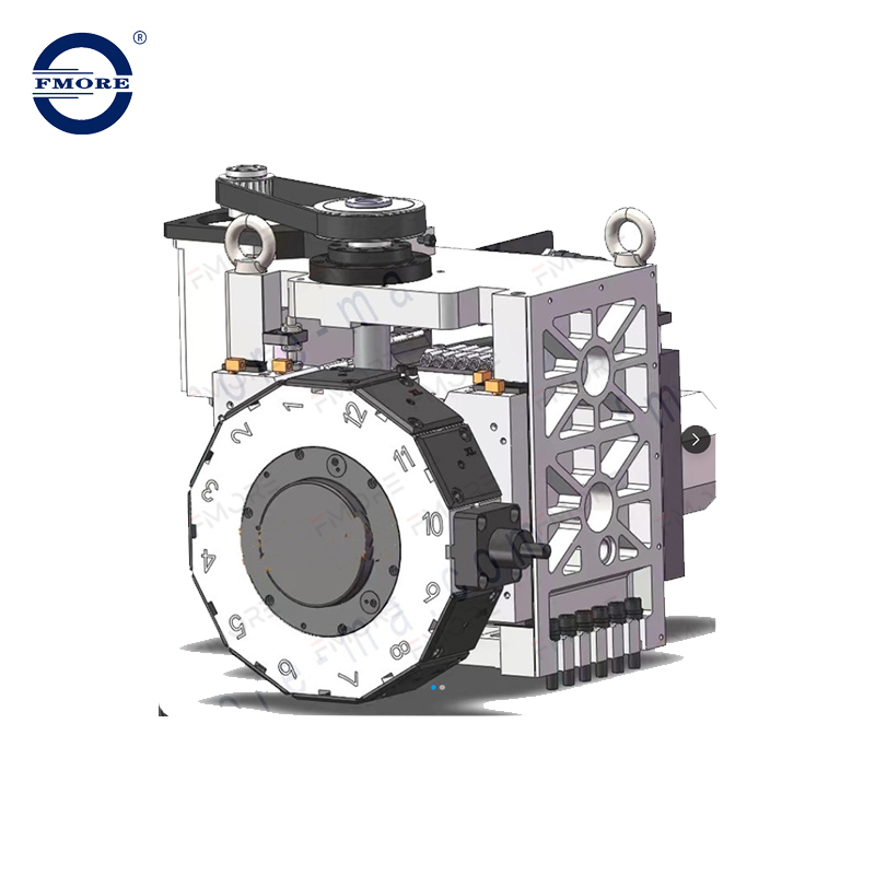
The mechanical travel of the Y-axis is useless without the right tooling interface. You are essentially turning your lathe into a horizontal mill. This puts tremendous stress on the powered tool turret. You must evaluate the live tooling RPM, available torque, and duty cycles. Milling a deep pocket in 4140 steel requires sustained torque that intermittent drilling does not. The drive mechanism inside the turret must handle continuous milling loads without overheating or stalling.
Tooling interfaces dictate how well the machine handles these loads. The industry generally splits between VDI and BMT designs. VDI uses a serrated shaft that pulls the toolholder into the turret face. It is fast to set up. However, it relies on a single clamping point. When you apply heavy Y-axis side loads during milling, VDI shanks can flex or chatter.
A BMT tool turret (Base Mounted Turret) solves this rigidity problem. BMT holders bolt directly to the face of the turret using four heavy cap screws and precision locating keys. This wide stance distributes cutting forces across a much larger surface area. It provides the lateral rigidity required for aggressive Y-axis milling. If you plan to mill steel or run large endmills, BMT is the only logical choice.
| Feature | BMT (Base Mounted Turret) | VDI (Verein Deutscher Ingenieure) |
|---|---|---|
| Mounting Method | Four bolts with locating keys on the turret face. | Single serrated shaft pulled into the turret bore. |
| Rigidity | Extremely high. Ideal for heavy milling and interrupted cuts. | Moderate. Prone to deflection under heavy side loads. |
| Setup Speed | Slower. Requires tightening multiple bolts and verifying alignment. | Fast. Single locking mechanism allows quick tool changes. |
| Alignment Accuracy | Keys lock the toolholder perfectly on center every time. | Requires manual indicating to ensure the tool is perfectly straight. |
Indexing speed also impacts your cycle times. A modern servo turret uses a dedicated servo motor to rotate the tool disc. This allows for rapid, non-stop bi-directional indexing. The turret takes the shortest path to the next tool. Once in position, high-force hydraulic or servo-driven couplings clamp the turret solid. This combination of speed and massive clamping force ensures the tool remains perfectly positioned, even under heavy interrupted cuts. You avoid the mechanical wear and tear associated with older Geneva-mechanism turrets.
Coolant delivery and chip management also require upgrades when utilizing live tooling. Milling deep pockets on a lathe creates chip evacuation problems because gravity does not pull the chips away from the cutting zone as effectively as it does on a vertical mill. High-pressure through-tool coolant becomes mandatory. You need enough PSI to blast chips out of blind holes before the endmill recuts them and snaps.
A Y axis turret offers incredible flexibility, but it has physical limits. You must objectively analyze the trade-offs before buying. The primary limitation is precision and rigidity under heavy load. Adding a Y-axis wedge or slide introduces more moving parts and a longer mechanical overhang. The cutting tool sits further away from the machine's base casting. While perfectly adequate for most parts, it is less rigid than a dedicated milling spindle on a high-end B-axis mill-turn machine.
Material hardness exposes these structural limits quickly. A Y-axis lathe easily mills aluminum, brass, and mild steel. You can push high feed rates and achieve excellent surface finishes. However, aggressive material removal rates in tough alloys like Titanium, Inconel, or hardened tool steels change the equation. Heavy milling in these materials causes vibration. The turret overhang magnifies this chatter, leading to poor tool life and compromised surface finishes. For high-volume aerospace alloys, a dedicated mill-turn center often performs better.
Physical stroke limitations also dictate part compatibility. A Y-axis does not offer the massive travel of a vertical mill. Typical Y-axis travel ranges from +/- 2 to 4 inches, depending on the machine's frame size. This travel is usually split evenly above and below the centerline. You must evaluate your part size against these constraints. If you need to mill a 6-inch long flat on a large diameter flange, a standard Y-axis might run out of stroke before finishing the cut.
Capital expenditure and floor space requirements heavily favor the Y-axis lathe. A full 5-axis mill-turn center with a dedicated milling spindle and tool changer requires a massive initial investment. It also consumes significant floor space and requires complex maintenance. A lathe with a Y-axis offers 80% of the capability for a fraction of the cost and footprint. It fits into standard turning cells easily.
When evaluating your shop's needs, consider these specific operational constraints:
Maximum Tool Weight: Turrets have strict weight limits for live tools. Exceeding this causes indexing errors and premature servo wear.
Clearance Envelopes: Long boring bars mounted next to live tools can easily strike the sheet metal or tailstock during a Y-axis move.
Spindle Lock Rigidity: The main spindle must have a robust C-axis brake to hold the part perfectly still while the Y-axis mills heavy flats.
Calculating ROI for a Y-axis machine requires looking past the initial purchase price. You are buying cycle time reduction and process stability. The primary financial return comes from eliminating secondary operations. When you drop a finished part into the parts catcher, you eliminate the labor required to move that part to a mill. You eliminate the queue time waiting for a mill to open up. You eliminate the cost of designing and machining custom soft jaws for the second operation.
Let us look at a practical shop floor scenario. You are machining a batch of 500 stainless steel shafts with a threaded cross-hole. On a standard 2-axis lathe, the turning takes three minutes. The parts then sit in a bin for two days waiting for the vertical mill. The mill setup takes two hours. The actual milling cycle takes one minute per part. The operator has to load and unload 500 times. With a Y-axis lathe, the turning and milling happen in one four-minute cycle. The parts come off the machine ready to ship. You save hours of setup time, days of queue time, and hundreds of manual part handling steps.
Reduction in scrap generates massive hidden savings. "Done-in-One" machining removes human error from part transfers. Every time an operator loads a turned part into a mill vise, there is a risk of misalignment. A chip under the part ruins the perpendicularity. Clamping too hard distorts thin walls. By keeping the part in the lathe chuck and using the Y-axis to finish the milling, you maintain absolute control over the datum. Scrap rates plummet, and feature-to-feature accuracy becomes highly predictable. You stop throwing away expensive material because of a simple loading error on the second operation.
You also reduce tooling redundancy. When you split operations across two machines, you often need duplicate drills, taps, and endmills for both the lathe and the mill. Consolidating the work into a single machine reduces your overall tooling inventory and simplifies tool life management.
Hardware is only half the battle. Implementing a Y-axis requires upgrading your software infrastructure. Manual conversational programming at the control becomes highly inefficient for complex off-center milling. You need advanced CAM software capable of simulating Y-axis toolpaths accurately. More importantly, you need a proven, bug-free post-processor. A bad post-processor will output incorrect Y-axis coordinates, leading to scrapped parts or catastrophic machine crashes.
Tool interference and clearance management become daily challenges. Turret crowding is a reality. Adding Y-axis travel means the tools move up and down in a confined space. You increase the risk of long boring bars or live tools crashing into the chuck, the tailstock, or the sheet metal enclosures. Rigorous digital twin simulation in your CAM software is mandatory. You must model the exact toolholder lengths and chuck jaw dimensions to verify clearance before pressing cycle start. You cannot rely on the operator overriding the rapid feed rate to catch a collision. The kinematics are too complex.
Operator skill levels must scale with the machine's complexity. Transitioning from standard 2-axis turning to multi-axis setups involves a steep learning curve. Machinists must understand how to touch off tools in three axes. They need specialized training in live tool maintenance, alignment, and rebuilding. A misaligned live tool holder will destroy endmills and ruin Y-axis tolerances. Invest heavily in operator training during the machine installation phase. Teach your setup personnel how to properly indicate a BMT holder and how to verify the C-axis brake engagement.
To maximize your production efficiency and determine if a Y-axis lathe fits your manufacturing workflow, execute the following steps:
Audit your current part families to identify components requiring off-center drilling, flats, or keyways that currently force secondary mill setups.
Calculate the exact labor hours, fixture costs, and scrap rates associated with your existing secondary milling operations to establish a baseline for ROI.
Request a time study and a physical test cut from the machine tool builder using your most complex part and toughest material.
Verify that your current CAM software package supports Y-axis kinematics and secure a guaranteed, proven post-processor before finalizing the machine purchase.
A: A C-axis rotates the main spindle to position the part, but the cutting tool only moves in X and Z. A Y-axis moves the tool orthogonally up and down relative to the centerline. This enables true off-center machining and flat wall milling without rotating the part.
A: Yes, it is possible by interpolating X, Y, Z, and C axes simultaneously. However, 3D surfacing is generally limited by the live tool's rigidity and maximum RPM. A dedicated milling machine handles complex 3D contours much faster and with better surface finishes.
A: BMT mounts securely to the turret face using four bolts and precision locating keys. This wide clamping footprint provides superior lateral rigidity. It prevents tool deflection when absorbing the heavy side loads generated during aggressive Y-axis milling operations.
A: Standard industry travel ranges from +/- 2 inches to +/- 4 inches, depending on the physical size of the lathe. This travel is usually split evenly above and below the spindle centerline, limiting the maximum off-center distance you can reach.
A: Yes, slightly. The extra slide or wedge mechanism introduces more mechanical joints and increases the tool's overhang from the base casting. This can reduce heavy roughing capability during turning compared to a standard 2-axis box-way lathe.
A: While simple off-center holes can be programmed manually at the control, complex milling requires robust CAM software. The software must feature accurate machine kinematics simulation and a proven post-processor to prevent tool interference and crashes in the confined work envelope.

