
- All
- Product Name
- Product Keyword
- Product Model
- Product Summary
- Product Description
- Multi Field Search


Views: 0 Author: Site Editor Publish Time: 2026-11-18 Origin: Site


Have you ever watched a perfectly good shaft turn into scrap because of violent lathe vibration? This phenomenon does more than just ruin surface finishes. It shatters carbide inserts, accelerates spindle wear, and destroys tight dimensional tolerances. In the realm of precision machining, hitting that mirror-like finish is the baseline. Yet, operators constantly battle the nightmare of vibrational instability.
When turning long or slender parts, managing these destructive lateral forces requires a solid structural anchor. Relying on the chuck and tailstock alone is a mathematical recipe for deflection. In this comprehensive guide, we will walk through exact setup optimizations. We will show you how to kill deflection through precise calibration and strategic equipment selection.
Core Machining Principles:
Vibration Diagnostics: Distinguishing between machine resonance, forced vibration, and harmonic regenerative feedback is the first step toward an effective empirical solution.
Structural Anchoring: A properly calibrated support mechanism significantly reduces the unsupported span of the material to prevent mid-span bending.
Clamping Force Mastery: Identifying the optimal pressure zone dictates success. Insufficient force allows micro-bouncing, while excessive clamping induces runaway thermal expansion and severe scoring.
Systematic Optimization: Rigorous lubrication protocols, precise alignment, and matching the contact roller material to the workpiece are foundational for a rigid cutting environment.
In the daily grind of precision turning, chatter is a highly destructive force that compromises both the dimensional accuracy and the surface integrity of a machined component. To effectively eliminate it, machinists must first understand the underlying physics causing a machine tool to resonate violently. This vibration typically falls into two primary categories. The first is forced vibration, and the second is self-excited vibration, commonly referred to as regenerative harmonic feedback.
Forced vibration is strictly mechanical in origin. It can be traced back to unbalanced chucks, worn spindle bearings, damaged drive belts, or interrupted cuts caused by the geometry of the part itself. Because the frequency of forced vibration matches the rotational speed of the spindle or the frequency of the mechanical defect, it is relatively straightforward to diagnose. You simply inspect the rotating hardware.
In contrast, regenerative feedback is far more complex and insidious. It occurs when the cutting tool encounters microscopic irregularities left by the previous rotation of the workpiece. As the carbide insert rides over these microscopic waves, the cutting force fluctuates. This causes the tool and the workpiece to push away from each other. Consequently, this creates a new and often amplified wave on the current pass. If the phase shift between these successive waves aligns unfavorably, the vibration feeds on itself. It grows exponentially until the entire machine resonates with a deafening squeal.
Long and slender workpieces are inherently susceptible to this physical reality. In mechanical engineering, the rigidity of a cylindrical shaft is inversely proportional to the cube of its length. When the Length-to-Diameter ratio exceeds six to one, the natural stiffness of the steel is no longer sufficient to resist lateral cutting forces. Without adequate structural support, the mid-span of the workpiece acts exactly like a plucked guitar string. It bows and vibrates violently upon contact with the cutting edge.
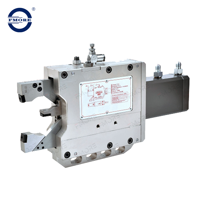
When machining components with a high Length-to-Diameter ratio, relying solely on the chuck and the tailstock center is physically insufficient. While the tailstock secures the far end of the shaft, the center of the workpiece remains entirely vulnerable to tool pressure. This is precisely where a steady rest becomes an indispensable piece of your machining arsenal.
This device functions by introducing a rigid intermediate support node along the length of the rotating workpiece. By effectively dividing the unsupported span into two shorter sections, the support exponentially increases the overall dynamic stiffness of the part. Placing a support exactly at the midpoint of a shaft reduces the effective unsupported length by half. According to fundamental beam deflection formulas, this localized intervention increases the stiffness of that specific section by a massive factor of eight.
Furthermore, this localized rigidity is mandatory for maintaining tight geometric tolerances. Without it, the lateral force exerted by the cutting tool will push the material away. This results in a tapered or barrel-shaped profile rather than a perfect cylinder. The support mechanism also absorbs and dampens high-frequency vibrations before they can propagate along the shaft and evolve into severe regenerative feedback.
Integrating this mechanism requires spatial awareness and absolute cleanliness. The device must be mounted securely to the lathe bed, and its three contact points must be perfectly concentric with the spindle axis. When executed correctly, this configuration transforms a flexible rod into a highly machinable structure. Operators can then utilize aggressive feed rates and heavy depths of cut without fear of catastrophic tool failure.
The effectiveness of your support system hinges entirely on one critical variable. Applying the correct pad pressure against the rotating workpiece is a delicate balancing act that requires empirical observation, tactile feedback, and technical precision. Veteran machinists often refer to this as finding the optimal zone where the clamping force is neither too loose nor too tight.
When the contact pads do not exert enough force, the workpiece is allowed to float within the jaws. This microscopic clearance defeats the entire purpose of the structural anchor. As the cutting tool engages the material, the shaft will deflect slightly until it bottoms out against the loose pads. This bouncing effect creates intermittent contact. It immediately translates into severe tool chatter and an erratic surface finish. Insufficient clamping also fails to provide the necessary dampening effect, allowing harmonic vibrations to travel freely.
Conversely, applying excessive clamping force introduces a host of severe mechanical and thermal issues. Over-tightening the jaws forces the pads to aggressively rub against the rotating shaft. This excessive friction rapidly generates intense heat. As the workpiece heats up, thermal expansion occurs. Because the diameter of the heated shaft increases while the support jaws remain fixed, the friction compounds continuously. This runaway thermal cycle inevitably leads to deep scoring of the metal surface, premature degradation of the contact rollers, and permanent bending of the workpiece.
Thermal dynamics must be actively managed during long turning cycles. A shaft that is perfectly dialed in at room temperature may become dangerously tight after ten minutes of heavy roughing. Seasoned operators anticipate this expansion. They utilize proper high-pressure coolant application and periodically verify the tension by hand to ensure the friction remains within safe operational limits.
Achieving the optimal clamping setting is a systematic process that relies on careful measurement rather than guesswork. A rigorous lathe setup procedure ensures repeatability and safeguards both the expensive workpiece and the machine tool itself.
Preparation and Cleaning
Before mounting the workpiece, wipe down the bed ways with a lint-free cloth. Ensure the lathe bed, the base, and the contact pads are immaculately clean. Even a single stray metal chip trapped under the heavy iron base can tilt the assembly, throwing the entire system out of concentricity.
Establishing Concentricity
Never use the support jaws to force a bent shaft into alignment. First, secure the workpiece between the chuck and the tailstock center. Use a dial test indicator to sweep the section of the shaft where the support will be positioned. Ensure the runout is within acceptable tolerances. If the shaft is excessively warped, it must be physically straightened before machining commences.
Advancing the Lower Pads
Position the heavy frame over the desired support point and clamp it firmly to the bed. Begin by advancing the two lower pads, typically positioned at the four and eight o'clock positions. Bring them into light contact with the workpiece. Use a dial indicator resting on top of the workpiece to monitor its vertical position. The lower pads should touch the material intimately without lifting it off its natural centerline.
Setting the Top Pad and Final Tension
Once the lower pads are supporting the weight and maintaining the centerline, advance the top pad at the twelve o'clock position. The adjustment here requires refined tactile feedback. The pad should make firm contact, yet you should still be able to rotate the chuck by hand with moderate and smooth resistance. For high-precision setups, utilize torque indicators on the adjustment screws to ensure uniform tension across all three points.
Implementing Boundary Lubrication
Friction is the ultimate enemy of a static support setup. Before engaging the spindle, apply a high-pressure boundary lubricant directly to the contact zone. Heavy way oil or specialized anti-seize compounds loaded with molybdenum disulfide work best. Proper lubrication creates a vital hydrodynamic film that separates the pad material from the rotating steel. This drastically reduces heat generation and prevents catastrophic galling.
Understanding workpiece deflection is crucial for precision engineering. Deflection is not uniform across a shaft. Rather, it follows a predictable parabolic curve, with the maximum bending typically occurring at the exact midpoint between two support nodes. Therefore, the strategic placement of your support mechanism and the careful selection of appropriate contact materials are vital.
The material composition of the contact points drastically influences both the friction coefficient and the risk of surface marring. To make the best engineering decision, refer to the following material comparison:
| Contact Material | Friction Coefficient | Wear Resistance | Optimal Application Scenario |
|---|---|---|---|
| Cast Bronze | Medium | High | Heavy-duty roughing on large steel shafts. Requires constant boundary lubrication. |
| Hardened Steel Rollers | Low (Rolling) | Very High | High-RPM turning and precision CNC grinding. Susceptible to chip embedment. |
| PTFE / Nylon | Very Low | Low | Finishing passes on delicate materials like polished aluminum or brass. Low heat tolerance. |
Furthermore, the geometry of the workpiece dictates your support strategy. A solid steel bar has inherent mass and rigidity, allowing it to absorb vibrational energy. A hollow thin-walled tube acts as an acoustic resonator and is highly susceptible to crushing if the clamping force is too high. When supporting hollow tubes, operators must use wider contact points to distribute the radial load. Inserting a tight-fitting structural plug into the inner diameter of the tube is often necessary to prevent the walls from collapsing under pressure.
Selecting the correct support mechanism is not a guessing game. It requires matching the physical specifications of the tool to your production demands. For instance, modern self-centering hydraulic units designed for precision CNC turning and grinding offer massive upgrades over manual cast-iron models.
When evaluating a unit, look at the clamping range and repeatability. High-end hydraulic models typically feature broad clamping ranges, such as 20mm to 165mm, or larger heavy-duty models spanning 50mm to 250mm. This versatility allows a single machine to handle diverse part families. More importantly, precision roller mechanisms in these advanced units maintain a centering repeatability of 0.005mm. This micro-level precision ensures that when the hydraulic arms close, the centerline of the workpiece remains absolutely perfectly aligned with the spindle axis, eliminating induced runout.
In recent years, the precision machining industry has seen a massive shift toward adaptive control systems and smart manufacturing. Current industry trends indicate a growing integration of sensor-equipped support mechanisms. These advanced units can monitor contact friction, radial load, and pad temperature in real-time.
This technological evolution allows modern CNC controllers to automatically adjust hydraulic clamping pressure on the fly. If the sensors detect a rapid temperature spike indicating thermal expansion, the system micro-adjusts the jaw tension before catastrophic surface scoring occurs. While fully automated hydraulic systems are becoming the standard in high-volume aerospace and automotive production facilities, the fundamental principles of mechanical calibration remain absolutely vital for custom job shops and legacy equipment operators.
Even with meticulous preparation, machinists may occasionally encounter unexpected vibrations or dimensional inaccuracies. Systematically troubleshooting your setup is absolutely essential for isolating the root cause of the problem before it ruins an expensive piece of bar stock.
If your workpiece exhibits a taper despite using a support, the most common culprit is subtle misalignment. If the center of the support is not perfectly collinear with the spindle axis and the tailstock center, the workpiece is being forced into an unnatural bow shape. To diagnose this, mount a dial indicator on the carriage and run it along the length of the workpiece. A steady linear deviation indicates that the support jaws are pushing the material off-center.
When high-pitched squealing suddenly appears, do not immediately assume the support jaws are at fault. A worn spindle bearing can produce harmonic vibrations that perfectly mimic mid-span deflection. To isolate the issue, perform a test cut close to the chuck without the support engaged. If the rough finish persists near the chuck, the spindle bearings or chuck jaws are likely compromised. If the cut is smooth near the chuck but degrades as the tool moves toward the middle of the part, the issue is definitively related to mid-span bending.
Finally, a common error is using the wrong type of support for the specific operation. A stationary unit bolted to the bed is ideal for supporting the end of a long shaft for internal boring. However, if you need to turn a very slender precision lead screw across its entire length, a stationary unit is insufficient. In this scenario, a follower rest that bolts directly to the traveling carriage is required to provide localized resistance exactly opposite the cutting tool.
Mastering the delicate relationship between structural support and clamping force is a true hallmark of a skilled machinist. By controlling bending forces and systematically eliminating the root sources of vibration, you can turn even the most challenging slender parts with absolute confidence. Remember that every machining scenario is unique. Take the time to calibrate your equipment correctly, monitor your heat levels closely, and adjust your tension incrementally.
Proper structural support not only prevents costly scrap rates on slender parts but ultimately creates vastly superior products. If your shop is struggling with chatter, poor surface finishes, or excessive insert wear, it is time to evaluate your workholding strategy. For industry-leading precision, explore the advanced hydraulic and manual support solutions at Fmore CNC to find the exact mechanism engineered for your specific turning or grinding application.
If the workpiece shows visible score marks, gets excessively hot to the touch after a short period of turning, or shows signs of deflection toward the center of the bar, your clamping force is likely too high. You may also notice the lathe motor laboring or smell burning boundary lubricant.
While it is the most effective mechanical tool for dampening vibration in long parts, it must be paired with correct tool geometry, sharp inserts, and optimal machining parameters like speed and feed to be fully effective. It is a critical piece of the puzzle, but not a magic cure-all for dull tooling or poor programming.
Cast bronze is the traditional industry standard due to its immense compressive strength and self-lubricating properties, making it perfect for heavy roughing. However, nylon, PTFE, or high-density plastic materials are excellent alternatives for preventing surface marring on delicate or pre-finished parts like polished aluminum.
Generally, no. For short and highly rigid parts, the chuck and tailstock provide more than sufficient stability. These support mechanisms are specifically reserved for setups with high length-to-diameter ratios that naturally invite bending and harmonic vibration.
If you are making an aggressive roughing pass that generates significant heat, you should stop the spindle and check the tension periodically. Thermal expansion can cause the metal to swell rapidly, turning a perfectly adjusted setup into an over-tightened hazard within a matter of minutes.
In standard steel turning operations, a Length-to-Diameter ratio exceeding 6:1 generally requires tailstock support. Once the ratio surpasses 10:1 or 12:1, a center-mounted steady rest becomes mandatory to prevent catastrophic mid-span deflection and maintain safe machining conditions.
Every mechanical setup has a natural resonant frequency. If your spindle RPM matches this exact frequency, the vibration will amplify exponentially. Simply altering your spindle speed by ten to fifteen percent can disrupt this harmonic resonance, often eliminating the chatter instantly without changing the physical setup.

