
- All
- Product Name
- Product Keyword
- Product Model
- Product Summary
- Product Description
- Multi Field Search


Views: 0 Author: Site Editor Publish Time: 2026-11-05 Origin: Site


You just optimized your G-code to shave three seconds off a cycle time. The spindle ramps up. Coolant blasts the window. Suddenly, a terrifying "thunk" echoes across the shop floor. The workpiece just shifted out of alignment.
If you have ever cranked the RPM and watched a part slip, you know the invisible enemy of high-speed turning. At its core, this is a strict physics problem. Rotational forces pull the jaws outward during fast cycles. This fights directly against your clamping mechanism. Understanding how to manage this phenomenon is critical for operator safety, part accuracy, and long-term machine health. In this technical guide, we break down exactly why this happens. You will also learn how to optimize your lathe chuck setup to completely eliminate grip loss.
Speed Kills Hold: As rotational velocity increases, the outward force acting on the jaws increases exponentially. This drastically reduces your effective holding power.
Mass Matters: The physical weight of your components is the primary multiplier of holding power loss. Lighter fixtures mean safer high-speed turning.
Static vs. Dynamic: The clamping pressure measured when the spindle is stopped is vastly different from the actual force holding the part at 3,000 RPM.
Modern Workholding Solutions: Advanced designs now feature internal compensation mechanisms to actively maintain pressure at elevated speeds.
Maintenance is Key: Proper lubrication and matching the right rotary cylinder to your setup are vital steps to prevent catastrophic failure.
Understanding the mechanics of workholding requires a clear look at the physics involved during rotation. When a machine operates at high velocity, the forces acting on the components change dramatically compared to when the equipment is at rest.
Centrifugal force acts as an invisible hand pushing objects outward from their center of rotation. Specifically in a CNC turning environment, this physical phenomenon forces the jaws away from the workpiece. It directly opposes the hydraulic cylinder.
The most critical factor to grasp is that this outward pull does not increase linearly. Instead, it increases with the square of the spindle speed. Double your RPM to reduce cycle times, and the outward pull on the jaws quadruples. Even a modest increase in velocity can result in a severe drop in effective clamping pressure. If this loss exceeds the initial force provided by the drawtube, the jaws will physically lift off the workpiece.
Relying exclusively on static measurements remains a surprisingly common and incredibly dangerous oversight in CNC programming. Static grip represents the clamping force applied to the workpiece when the spindle is at a complete standstill at zero RPM. Dynamic grip is the actual effective force securing the part when the spindle hits its target RPM. In stark contrast to a static measurement, dynamic testing reveals the true stability of your setup. A configuration that feels incredibly rigid at a standstill might retain less than a quarter of its holding power during an aggressive finishing pass.
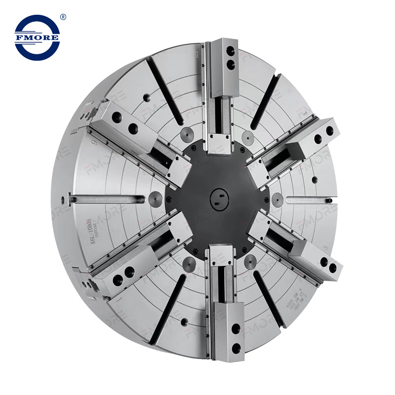
The physical mass of the components attached to your setup plays a massive role in how much clamping pressure vanishes during rotation. Consequently, selecting the right fixtures is a critical engineering decision that directly impacts shop floor safety.
In the mathematical formula for outward force, mass serves as a primary variable. Standard solid steel jaws significantly inflate the overall jaw weight. The heavier the component, the more violently it is pulled outward as the spindle spins.
Furthermore, the concept of the center of gravity cannot be ignored. When you utilize tall top jaws, the mass is shifted further away from the center. The further this center of gravity strays from the rotational axis, the longer the moment arm becomes. This extended leverage allows physical forces to easily pry the jaws open, exacerbating the loss of clamping pressure.
To mitigate this issue, operators frequently change the material of the top jaws. While standard steel is undeniably durable, it is also dense and heavy. By transitioning to lightweight alternatives like high-strength aluminum or titanium, machinists can instantly slash the mass by up to 60 percent. This dramatic reduction in bulk directly translates to a proportional drop in outward pull. Lighter components empower operators to run machines at higher safe speeds without sacrificing dynamic stability.
Identifying instability before it results in a scrapped part or a devastating machine crash is essential for maintaining production efficiency. Pay close attention to these physical indicators on the shop floor.
The most glaring symptom of insufficient dynamic holding power is workpiece slippage. During heavy Z-axis roughing, the cutting tool exerts immense axial pressure on the metal. If the dynamic pressure has plummeted due to excessive RPMs, the friction breaks. The part will physically push back deeper into the bore. This destroys your Z-axis zero point and causes subsequent features to be machined entirely out of tolerance.
Additionally, when a part lacks rigid support, it becomes highly susceptible to micro-vibrations induced by the cutting tool. This harmonic instability is often the direct result of a weakened hold. You will see these vibrations manifest as distinct chatter marks on the machined surface. This instantly ruins the finish. This constant vibration also causes premature micro-chipping on carbide inserts, forcing operators to swap cutting tools more frequently and driving up consumable costs.
If you program a perfectly straight cylinder but the resulting part measures with a taper, instability is a likely culprit. When clamping pressure is compromised, cutting forces cause the workpiece to pivot slightly within the jaws. As the tool travels further from the face, this deflection amplifies, resulting in out-of-tolerance tapered cuts.
Looking at current manufacturing trends, especially in EV components and aerospace, shops are pushing cycle times to the absolute limit. Data shows a massive shift away from traditional solid-body systems. Modern facilities now demand workholding that safely operates above 4,000 RPM without sacrificing concentricity. Raw rotational velocity is useless if the equipment cannot guarantee absolute part security.
To address the inherent physics of high-speed turning, manufacturers have engineered advanced solutions. State-of-the-art systems feature built-in compensation. These sophisticated designs utilize internal counter-weights mechanically linked to the master jaws. As the spindle accelerates and outward forces pull the jaws away from the part, those exact same forces pull the internal counter-weights outward.
Because these weights are connected via a precision lever mechanism, their outward movement actively forces the jaws inward. This mechanical cancellation effectively neutralizes the centrifugal loss. It allows the system to maintain a near-constant clamping pressure from a dead stop all the way to its maximum rated speed.
Beyond active counter-weights, the foundational architecture of hydraulic systems has evolved. High-accuracy hydraulic chucks are now manufactured with exceptionally tight tolerances and optimized geometries. By steepening the angles of the internal wedges, engineers increase the mechanical advantage. These structural enhancements provide a much more rigid baseline, lowering labor intensity through high automatic levels and ensuring consistent part concentricity.
| Feature | Traditional Solid-Body Chuck | High-Accuracy Hydraulic Chuck |
|---|---|---|
| Dynamic Grip Retention | Loses up to 80% at max RPM | Maintains near 100% via active compensation |
| Automation Level | Manual or basic hydraulic assist | High automatic level, less labor intensity |
| Concentricity & Precision | Prone to runout at high speeds | Strictly maintained wedge-hook tolerances |
| Best Application | Low-speed roughing, heavy castings | High-speed turning, aerospace, EV parts |
Achieving a secure hold on a workpiece is not solely the responsibility of the jaw face. The entire system operates as a synchronized kinematic chain. To fully combat rotational force loss, engineers must evaluate the synergy between the hydraulic rotary cylinder, the drawtube, and the internal wedge mechanism.
First, match the rotary cylinder to the drawtube precisely. The hydraulic rotary cylinder is the powerhouse of the setup. If the rotary cylinder is undersized for the specific model, the baseline gripping force will be fundamentally compromised before the spindle even begins to rotate. A weak baseline means the setup lacks the necessary buffer to survive the inevitable loss as the spindle accelerates.
Second, size hollow systems correctly. Hollow designs featuring an open center present unique hardware matching challenges. The through-hole limits the internal physical space available for the wedge-hook mechanism. When sizing a rotary cylinder, operators must strictly adhere to the manufacturer maximum drawbar pull specifications. Applying excessive drawbar pull will push the internal wedge hooks beyond their structural yield points, permanently deforming the equipment.
Finally, implement strict lubrication routines. A poorly maintained, dry internal mechanism can lose up to 50 percent of its drawbar pull to internal friction before the jaws even make contact with the part. Regular greasing using the recommended lubricant is non-negotiable for high-speed operations.
Physical loss during rotation is an unavoidable law of nature, but it is entirely manageable with the right engineering approach. By carefully controlling component mass, monitoring your speeds, and maintaining your equipment with rigorous lubrication schedules, operators can machine safely and efficiently.
If your manufacturing facility is transitioning toward high-speed, high-volume production to reduce cycle times, continuously fighting with older equipment is a false economy. The costs associated with poor stability—scrapped parts, premature tool wear, and extensive machine downtime following a crash—far outweigh the initial capital investment of modernizing your shop.
Do not let invisible physical forces ruin your parts or endanger your machinists. Take the time to regularly test your dynamic holding power. We highly recommend upgrading to a high-accuracy hydraulic chuck with a high automatic level to reduce labor intensity and guarantee precision. Explore the advanced workholding solutions at Fmore CNC to find the perfect hardware synergy for your high-speed turning applications.
The exact amount of force lost at maximum speed depends entirely on the physical size of the unit, the design of the internal mechanisms, and the total mass attached to the face. However, empirical testing shows that without any active compensation, a standard setup can lose between 50 and 80 percent of its static hold when operating at its maximum rated RPM. Using heavy, oversized steel components can cause the system to lose 100 percent of its effective hold before even reaching maximum RPM, resulting in immediate workpiece ejection.
No, increasing the hydraulic pressure beyond the specified limits is a highly dangerous practice. The internal wedge-hook mechanism relies on precise, angled sliding surfaces. Forcing the rotary cylinder to pull harder subjects these internal angles to extreme stress. This breaks down the lubrication boundary layer and leads to severe metal-to-metal galling. Eventually, excessive drawbar pull will permanently deform the body, causing the master jaws to bind in their guideways and ruining the equipment entirely.
It holds workpieces by converting linear push or pull forces into radial clamping forces through an internal mechanical system, most commonly a wedge-hook or an internal scroll mechanism. A hydraulic cylinder pulls a drawtube connected to a central plunger. This plunger features angled wedges that interlock with corresponding hooks on the bottom of the master jaws. As the plunger is pulled backward, the angled wedges force all three master jaws to slide inward simultaneously. Because the wedges are machined to identical tolerances, the jaws move in perfect unison, automatically centering the workpiece while applying evenly distributed pressure.
Larger units are restricted to lower maximum speeds due to the fundamental physics of rotational mass. Outward force is calculated by multiplying the mass of the object by its distance from the center of rotation and the square of its rotational speed. A larger unit inherently possesses much heavier master jaws, and its larger diameter means the center of gravity is located much further away from the spindle centerline. Manufacturers strictly govern larger units with lower RPM limits to keep these immense forces within safe structural operating margins.
The calculation relies on the standard physics formula for rotational force: F = m * r * w^2. In this equation, 'm' represents the total mass of the top jaw and master jaw, 'r' is the distance from the spindle centerline to the jaw's center of gravity, and 'w' is the angular velocity derived from your RPM. Because the velocity is squared, even minor increases in RPM generate massive spikes in outward force. For practical shop floor applications, always consult the dynamic grip loss charts provided by your manufacturer rather than calculating manually.
The maximum safe speed is not a universal number; it is strictly dictated by the specific model, its outer diameter, and the weight of the top jaws currently installed. A 6-inch high-accuracy hydraulic chuck might safely operate at 6,000 RPM, while a 15-inch model from the same product line may be hard-capped at 2,500 RPM. You must always reference the manufacturer specifications engraved on the faceplate and adjust downward if you install custom, oversized, or unusually heavy top jaws.

