
- All
- Product Name
- Product Keyword
- Product Model
- Product Summary
- Product Description
- Multi Field Search


Views: 0 Author: Site Editor Publish Time: 2026-11-11 Origin: Site


Selecting the right positioning equipment is just the start when upgrading your CNC setup or designing a custom automated cell. The real secret to flawless machining is how well that fixture holds its position under immense cutting forces. This is where the braking system steps in. Picture a massive end mill plunging into a block of aerospace-grade titanium. If the fixture shifts even a fraction of a millimeter, the entire workpiece is ruined. A weak clamp leads to chatter, poor surface finishes, and scrapped parts. The right mechanism, however, guarantees absolute rigidity.
With various options on the market, ranging from pneumatic clamps to heavy-duty fluid systems, selecting the perfect setup requires technical insight. In this engineering guide, we break down the available technologies, their impact on machining precision, and the exact specifications you need to evaluate before making a critical purchasing decision.
Holding Torque is Crucial: The primary function of a clamping mechanism is providing sufficient torque to resist cutting forces. This ensures exceptional precision during aggressive milling operations.
Hydraulic Systems for Heavy Duty: Pressurized fluid systems remain the industry standard for high-torque applications. They offer massive holding force and unmatched structural rigidity.
Pneumatic Clamps for Speed: Air-driven brakes are ideal for lighter loads and high-speed positioning. They are perfect for clean-room environments where fluid contamination poses a severe risk.
Electronic Integration Matters: Modern braking systems must seamlessly communicate with your machine controller. This ensures rapid engagement without causing mechanical wear.
Consistent Precision: The right clamping setup eliminates micro-movements during machining. This directly improves the consistency of your production runs across thousands of continuous cycles.
A programmable multi-axis device integrated into CNC machinery positions workpieces at exact angles for complex machining operations. Controlled by the machine's numerical control system, it allows operators to cut complex geometries without manual repositioning. Reaching the correct angle is merely the first step. Holding that position securely while a cutter tears through raw metal is the real test.
You must distinguish between driving torque and holding torque. Driving torque is generated by the motor to rotate the fixture to the programmed coordinate. Holding torque is the static force required to keep the setup completely stationary while the tool engages the material. During aggressive drilling or boring, the cutter exerts tremendous lateral and rotational leverage. Relying solely on the motor's electronic hold is a recipe for disaster.
Operating an unbraked fixture introduces massive engineering risks. The setup experiences micro-movements when cutting pressures exceed the motor capacity. This lack of rigidity causes severe vibration. Chatter degrades the surface finish and ruins expensive tooling. A robust mechanical brake isolates the internal drive components from these violent forces. It transfers the load directly to the rigid cast-iron body.
Internal gearing does not define precision alone. It relies heavily on the stability from the clamping mechanism. Mechanical backlash is the slight clearance between mating gear teeth. It is a common inherent trait in worm gear systems. High-end manufacturing minimizes this clearance but cannot eliminate it entirely without causing excessive friction. A robust clamp physically locks the faceplate to the static housing. This action bypasses the internal gears. It eliminates mechanical backlash during the critical cutting phase, ensuring exceptional Indexing Accuracy.
Specifically, this locking action is fundamental for long-term consistency. In high-volume manufacturing, a fixture must return to the exact same angular position across thousands of cycles. If a clamp applies uneven pressure, the setup may settle in a microscopically different position each time. A consistent clamping force guarantees that the fixture is locked precisely where the encoder positioned it. This directly improves the Repeatability of your production runs.
Continuous cutting generates significant heat and vibrations. Thermal expansion transfers through the workpiece. An inadequate clamp allows these stresses to cause micro-shifting. The right brake acts as a rigid anchor. It dampens vibrations and resists thermal drift, thereby maintaining the strict geometric tolerances of the final product.
Recent industry analyses highlight a rapid shift toward automated hybrid braking systems. Manufacturers are pushing for higher material removal rates without sacrificing cycle times. Consequently, the demand for smart clamping mechanisms has surged. Facilities are moving away from purely manual setups. They favor systems offering real-time feedback. Modern equipment integrates seamlessly with advanced controllers to monitor clamping pressure dynamically. This trend underscores the importance of choosing a system tailored to strict industrial demands. Intelligent brakes prevent scrap by halting the machine if pressure drops below a safe threshold.
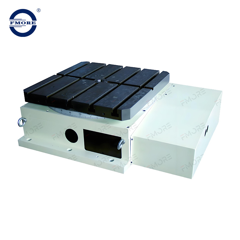
Understanding internal mechanisms is essential for specifying the correct equipment for your shop floor. Different clamping systems serve entirely different machining environments.
These systems use pressurized fluid to compress a specialized clamping sleeve against the rotating spindle. Standard industrial setups operate at high pressures between 35 and 70 bar. The primary advantage is exceptional clamping torque. Fluid is incompressible. It transfers massive amounts of force efficiently. This creates an incredibly rigid setup. For instance, premium positioning units like the NC Rotary Table series from Fmore CNC utilize advanced hydraulic clamping to deliver holding torques exceeding 1,200 Newton meters. This makes it the optimal choice for heavy milling involving tough materials like Inconel or tool steel.
The main drawback is the need for auxiliary infrastructure. A dedicated power unit is necessary if the machine lacks an existing circuit. These systems require regular maintenance to monitor fluid levels and filter conditions.
Air-driven clamps utilize compressed shop air to actuate the holding mechanism. Most facilities route standard air lines through solenoid valves to engage the clamp. Valued for cleanliness and simplicity, air systems use existing infrastructure. Air flows faster than viscous fluid. This provides quicker response times for engagement. They demand significantly less maintenance.
The fundamental limitation is lower clamping torque. Air clamps cannot withstand severe cutting forces due to lower operating pressures. They suit light-to-medium milling, aluminum machining, or automated assembly lines perfectly.
Typically built directly into the motor housing, these use electromagnetic coils to engage a friction disc against the motor shaft. They offer instantaneous electronic control. They require no external fluid lines.
However, these are secondary parking brakes rather than primary machining clamps. They hold the motor shaft instead of the faceplate. Any mechanical backlash in the gear train remains a factor. They are not recommended for resisting primary cutting forces in metalworking.
The debate between fluid and air systems depends entirely on your specific application and required material removal rates. When comparing torque, the difference is staggering. A Hydraulic Brake often provides three times the clamping power of its pneumatic counterpart. A 250-millimeter faceplate might offer 400 Newton meters of holding torque with air, but over 1,000 Newton meters with pressurized fluid.
Application matching is the most critical step. Choose a fluid-based system when cutting ferrous metals or utilizing large-diameter tools. The rigidity provided by incompressible fluid is unmatched. In contrast, opt for an air-driven system when machining softer materials like aluminum or integrating into high-speed assembly lines.
| Feature | Hydraulic Systems | Pneumatic Systems | Electromagnetic Brakes |
|---|---|---|---|
| Holding Torque | Extremely High | Low to Medium | Low |
| Response Time | Moderate | Very Fast | Instantaneous |
| Best For | Heavy milling, Titanium, Steel | Aluminum, High-speed indexing | Parking, Light assembly |
| Maintenance | Requires fluid and seal checks | Minimal | Zero maintenance |
Evaluating positioning equipment requires analyzing the engineering specifications deeply. Do not just look at the physical dimensions.
This is the most vital specification. It must confidently exceed the maximum rotational force generated by your cutting tool. Calculate the maximum cutting force in Newtons. Multiply it by the distance in meters from the center of the fixture to the point of the cut. Always incorporate a safety factor of at least 1.5 to account for tool wear and sudden material hardness variations. Premium indexers often feature dual-support braking systems to maximize this torque rating.
Every millisecond counts in high-volume production. Response time refers to how quickly the mechanism engages. Air-driven clamps actuate faster than fluid ones. A slow response time accumulates significant delays if an operation requires hundreds of indexing movements per hour. Evaluating the solenoid valve response is necessary for optimizing cycle speeds.
A mechanical clamp must work in perfect harmony with the CNC controller. Severe mechanical damage occurs if the timing is misaligned. The braking system must seamlessly communicate with your Servo Drive. Modern setups utilize precise logic controller dwell times. This ensures the drive holds the position electronically for a fraction of a second while the mechanical clamp engages. This prevents the motor from fighting the friction of a partially engaged brake.
Capital expenditure budgets often dictate that existing machinery must be utilized to its absolute maximum lifespan. Upgrading an older mechanical indexer to a fully programmable unit presents a highly cost-effective alternative to purchasing a new machining center. Shops can achieve complex multi-sided machining in a single setup.
Furthermore, retrofitting presents distinct engineering challenges. Manufacturing engineers often ask if an older pneumatic fixture can be upgraded to utilize pressurized fluid for increased holding torque. The physical execution is fraught with difficulty. Internal clamping sleeves within an air-driven unit are not engineered to withstand immense hydraulic pressure. Introducing fluid into a pneumatic mechanism will result in catastrophic seal blowout. This floods the internal gear housing with oil.
Upgrading requires seamless electrical integration with the machine’s legacy controller. The sequence must be perfectly synchronized with the drive to prevent mechanical conflict. Failure to properly program these logic gates will cause the motor to push against a partially engaged clamp. This leads to premature wear and a severe degradation of precision.
Different manufacturing sectors demand entirely different clamping strategies based on their unique operational constraints.
Machining operations frequently involve tough alloys such as titanium and forged steel. A heavy-duty fluid clamp is a fundamental requirement here. Any micro-vibration translates directly into chatter marks on a turbine blade. Fluid systems provide massive torque. They effectively turn the fixture and the machine bed into a single unyielding block of metal.
The medical device industry operates under different constraints. Cutting forces are generally much lower when producing delicate surgical instruments. Environmental regulations are exceptionally strict. The risk of fluid leaks contaminating a clean-room is unacceptable. Medical manufacturers heavily favor air-driven systems. They trade absolute torque for environmental cleanliness and rapid indexing speeds.
The daily production schedule is unpredictable for general job shops. A machine might cut soft aluminum enclosures on Monday and tough tool steel brackets on Wednesday. These environments require versatile equipment. Job shops often opt for high-torque air systems or compact units that run off air-over-oil intensifiers. This provides the cleanliness of an air system combined with holding power approaching that of a dedicated fluid unit.
While the electronic drive can theoretically hold the position, it is highly discouraged during actual machining operations. Relying solely on the motor to resist cutting forces causes the system to constantly hunt for its programmed coordinate. This generates excessive heat and can overpower the motor entirely. Always engage the mechanical clamp during cutting cycles.
Slippage is usually caused by inadequate fluid pressure, air trapped within the lines, or physical wear on the internal clamping sleeve. If the power unit fails to maintain the specified pressure, the holding force will proportionally decrease. Regular maintenance and inline pressure checks are required to ensure maximum rigidity.
A robust clamp prevents the fixture from shifting at a microscopic level when the cutter makes contact with the workpiece. By mechanically locking the internal gears and eliminating backlash, the fixture remains exactly where the encoder positioned it. This consistent rigidity ensures high repeatability from part to part.
Generally, no. The internal mechanisms and seals are engineered exclusively for either low-pressure air or high-pressure fluid. Applying high pressure to an air-based system will cause immediate seal blowout. Upgrading requires entirely new internal components engineered from the factory for those pressures.
Synchronization is handled entirely via the machine's programmable logic controller. Custom machine codes are integrated into the machining program. The logic sequence tells the drive to stop moving, commands the valve to open, and initiates a mandatory dwell time. This dwell time allows the components to physically move before the motor attempts to rotate again.
You must determine the maximum cutting force generated by your tool in Newtons. Multiply this force by the radial distance in meters from the center of the rotary faceplate to the exact point of cutting. This gives you the baseline torque. Always apply a safety multiplier of 1.5 to 2.0 to account for tool wear, vibration, and material inconsistencies.
Servo hold uses the electrical current of the motor to actively fight against rotational forces and maintain a position. It is dynamic and prone to micro-movements under heavy loads. A dedicated mechanical brake uses physical friction via air or fluid pressure to lock the spindle to the rigid housing. It provides a static, unyielding anchor that completely isolates the motor from cutting forces.
Selecting the correct clamping mechanism is a vital engineering choice. It directly impacts your machining success and overall profitability. Heavy milling requires the strong grip of fluid-based systems. High-speed light machining works best with clean air-driven alternatives. Match the mechanism to your specific daily shop applications. This ensures your equipment delivers flawless performance for years.
If you are looking to upgrade your machining capabilities with uncompromising rigidity and precision, explore the high-performance positioning solutions available at Fmore CNC. From heavy-duty hydraulic indexers to rapid pneumatic tables, you can find the exact equipment engineered for your shop's toughest demands. Evaluate your cutting forces, review your infrastructure, and invest in a system built to hold the line.

