
- All
- Product Name
- Product Keyword
- Product Model
- Product Summary
- Product Description
- Multi Field Search


Views: 0 Author: Site Editor Publish Time: 2026-08-16 Origin: Site


Machining long, slender, or heavy cylindrical workpieces introduces unavoidable physical realities: radial deflection, chatter, and harmonic vibration. Without adequate mid-span support, turning operations on high Length-to-Diameter (L/D) parts result in unacceptable runout, poor surface finish, accelerated insert wear, and high scrap rates. Relying solely on tailstock pressure often bows the part or is impossible when end-face machining is required. Selecting the correct workholding support requires moving beyond basic dimensions to evaluate actuation methods, machine envelope constraints, and automation compatibility. This guide breaks down the technical criteria for evaluating and integrating the optimal Steady Rest for your specific turning applications.
L/D Ratio Dictates Necessity: Parts with an L/D ratio exceeding 6:1 (or 3:1 for aggressive roughing) mathematically require mid-point support to maintain tight geometric tolerances.
Automation Requires Self-Centering: High-volume CNC environments rely on the self centering steady rest to eliminate manual dial-in times and integrate directly with machine M-codes.
Clearance is Critical: Evaluating the physical interference between the steady rest body, the cutting tool path, the turret, and the machine doors is the most common failure point in procurement.
Actuation Dictates Clamping Force: The choice between hydraulic, pneumatic, and manual actuation directly impacts clamping rigidity, cycle times, and integration costs.
Understanding the physical limitations of unsupported turning establishes the baseline criteria for requiring additional workholding. Cutting forces constantly push the workpiece away from the cutting tool. This radial pressure creates geometric errors that compound over the length of the part. When you machine a shaft held only by a chuck, the unsupported end acts as a lever. The longer the lever, the less force required to bend it.
Industry standards dictate specific thresholds for deflection based on the Length-to-Diameter (L/D) ratio. An L/D ratio greater than 6:1 requires mid-span support for standard turning operations. For heavy interrupted cuts or aggressive roughing in tough materials like Inconel or 4140 pre-hardened steel, that ratio drops to 3:1. Tangential, radial, and axial cutting forces interact with workpiece rigidity constantly. The longer the part, the less rigid it becomes at the midpoint, leading to a barrel-shaped or hourglass-shaped profile depending on the toolpath.
| L/D Ratio | Machining Operation | Support Requirement | Expected Deflection Risk |
|---|---|---|---|
| Up to 3:1 | Standard Turning / Finishing | Chuck Only | Minimal to None |
| 3:1 to 6:1 | Heavy Roughing / Interrupted Cuts | Tailstock Required | Moderate (Chatter likely without tailstock) |
| 6:1 to 10:1 | Standard Turning | Tailstock + Mid-Span Support | High (Taper and harmonic vibration guaranteed) |
| 10:1+ | All Operations | Multiple Supports Required | Extreme (Part ejection risk without support) |
Success on the shop floor means achieving zero-taper turning. You must eliminate chatter marks completely to meet surface finish requirements. Maintaining concentricity across the entire Z-axis stroke is the ultimate goal. A properly integrated support system counteracts radial tool pressure directly at the source. It keeps the part on the true spindle centerline, allowing you to push feed rates and spindle speeds to their optimal limits without sacrificing insert life.
Tailstock support becomes physically impossible during deep hole drilling, internal boring, or facing the end of a long shaft. In these scenarios, the workpiece becomes a cantilevered beam. Cutting forces applied to the unsupported end cause massive vibration. If you try to bore a deep hole in a 30-inch shaft held only in the main spindle, the drill will walk off-center, and the boring bar will chatter violently.
Placing a support unit near the machining zone shifts the pivot point. It stabilizes the overhanging mass. This allows aggressive boring and facing operations without chatter. The support acts as a false tailstock, providing the rigidity needed for tight internal tolerances. You effectively reduce the cantilevered length to just the few inches protruding past the roller bearings, drastically increasing the dynamic stiffness of the setup.
Mechanical designs align with different production environments. Choosing the right category determines your cycle time, setup efficiency, and operator intervention requirements. A job shop running low-volume, high-mix parts has vastly different needs than a high-production automotive facility running thousands of identical transmission shafts.
Manual rests feature traditional three-point independent adjustment. Operators adjust each roller individually using threaded screws. This design fits low-volume, high-mix job shops where setup time matters less than initial equipment cost. Dialing in a manual unit requires skill, patience, and a dial indicator. The operator must sweep the part to ensure the rollers do not push the workpiece off the spindle centerline.
A Self Centering Steady Rest uses internal cam or lever mechanisms. These move all three rollers simultaneously to find the true center. This is essential for CNC automation. It handles varying bar stock diameters effortlessly and reduces operator intervention drastically. When the M-code fires, the arms close, and the geometry of the internal cams guarantees the rollers meet exactly at the spindle centerline, compensating for minor variations in raw stock diameter.
Manual Setup Procedure: Mount the base to the ways and lightly snug the bolts.
Turn a clean journal on the workpiece near the chuck.
Indicate the journal to ensure zero runout.
Bring the bottom two rollers into contact with the journal.
Bring the top roller down until it touches, then lock all adjustment screws.
Slide the entire assembly down the Z-axis to the required support position and lock the base.
Different mounting styles serve different machining strategies. You must match the mount to the operation and the physical layout of your lathe.
Fixed Rests: Mounted securely to the lathe bed or ways. They provide localized support and are perfect for end-face work, deep hole drilling, and general shaft turning where the toolpath does not need to cross the support point.
Traveling (Follow) Rests: Mounted directly to the carriage. They move synchronously with the cutting tool. This eliminates deflection exactly at the point of tool contact. They are essential for extremely long, ultra-thin shafts like lead screws or ball screws where the L/D ratio exceeds 20:1.
Retractable Rests: Advanced CNC-driven units. They automatically swing or retract out of the machining envelope via M-code. This allows the turret and carriage to pass without physical manual teardowns. These are common on multi-tasking machines and twin-spindle lathes.
Actuation methods determine clamping force and integration complexity. The choice depends on your machine's capabilities, the workpiece material, and the required cycle times.
| Actuation Type | Clamping Force | Actuation Speed | Best Application | Integration Requirements |
|---|---|---|---|---|
| Hydraulic | Very High (Up to 10,000+ lbs) | Moderate | Heavy forgings, aggressive roughing, solid bar stock. | Requires integration with the machine's hydraulic pump, manifold, and valve blocks. |
| Pneumatic | Low to Moderate | Very Fast | Thin-walled tubes, light workpieces, fast cycle times. | Requires clean, dry shop air and a simple solenoid valve. |
Hydraulic systems provide the massive clamping force required to hold heavy steel forgings against aggressive roughing cuts. However, applying too much hydraulic pressure to a thin-walled aluminum tube will crush it instantly. Pneumatic systems suit machines lacking auxiliary hydraulic circuits and provide a softer, faster clamp that prevents crushing delicate parts. You must regulate the pressure carefully regardless of the actuation method to balance support against deformation.
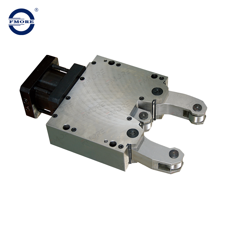
Ensure the selected hardware physically and functionally integrates with your existing CNC lathe. A mismatch here causes severe production delays, crashed machines, and wasted capital. You cannot simply buy a unit based on the chuck size; you must evaluate the entire machining envelope.
Evaluate dynamic load ratings carefully. The unit must support the static weight of the part plus the dynamic forces of machining. Undersized bearings fail quickly under heavy radial loads, leading to catastrophic part ejection. You must calculate the maximum weight of your heaviest part and ensure the roller bearings are rated for that load at your maximum intended RPM.
Analyze roller material options based on your process. Hardened steel offers excellent durability for raw stock and general turning. Carbide provides extreme wear resistance for abrasive materials or high-volume production runs. Synthetic or composite rollers prevent marring on pre-finished surfaces, which is critical when supporting a part on a previously ground or polished journal.
Mapping the machine envelope is a critical process. You must measure clearances meticulously. Highlight interference risks before purchasing by reviewing the 3D CAD models of the support unit against your machine's interior dimensions.
Verify turret indexing clearance. Ensure the longest boring bar in your turret will not strike the support body when indexing.
Check carriage pass-by clearance. The carriage must pass over or around the base without collision to reach the chuck.
Confirm sheet metal and door closures. The machine doors must shut completely with the unit installed and fully retracted.
Evaluate tailstock interference. Ensure the tailstock body does not collide with the support base when moving forward to engage the center.
Evaluate mounting configurations carefully. Flat bed, slant bed, box way, and linear guide mounting brackets all require specific base plate designs. A slant bed lathe requires a custom-angled bracket to ensure the arms close exactly on the spindle centerline.
How the unit relocates along the Z-axis ways impacts setup time and automation potential. Manual sliding relies on manual positioning and manual clamping of the base to the ways. It is slow but reliable, suitable for shops that rarely change part lengths.
Tow-Along or Jog-Assisted systems temporarily couple the base to the machine carriage using a hydraulic or pneumatic pin. Operators use the CNC handwheel to position it. This works even with the safety doors open under safe jog modes, drastically reducing setup time for varying part lengths. Fully programmable units use an independent servo axis or integrated hydraulic cylinder. They offer fully automated, M-code-directed positioning, allowing the machine to reposition the support mid-cycle without operator intervention.
Compare manual grease zerks against centralized automatic lubrication systems. Automatic systems reduce maintenance neglect. They ensure constant lubrication to internal cams and rollers, extending the life of the unit by thousands of hours. Manual greasing relies on operators remembering to hit the zerks every shift, which rarely happens in a busy production environment.
Evaluate chip ingress protection. Wiper seals, pressurized air purges, and enclosed cam mechanisms are mandatory. They help the unit survive high-pressure coolant and continuous chip flow. Without protection, fine cast iron dust or stringy steel chips destroy internal mechanisms, jamming the cams and causing the rollers to stick.
Operators face practical challenges during installation and daily use. Address these risks to maintain production efficiency and prevent scrap. Even the most expensive workholding system fails if installed incorrectly or maintained poorly.
A misaligned unit physically bows the workpiece. This induces taper, concentricity errors, and severe bearing wear. Alignment is non-negotiable. If the center of the rollers is even 0.002 inches off the spindle centerline, you will fight taper issues constantly.
The Quick-Set Method offers coarse alignment. Clamp the rollers onto a pre-turned section of the workpiece near the chuck where runout is zero. Then, slide or jog the base down the Z-axis to the designated support position. This works well for standard tolerances and general shaft work.
Ultra-Precise Alignment Method: Mount a precision-ground test arbor between the chuck and the tailstock center.
Mount a dual-axis dial indicator to the machine carriage.
Sweep the test arbor along the Z-axis to verify the tailstock is perfectly aligned with the spindle.
Position the support unit over the test arbor and close the arms lightly.
Sweep the top and side of the test arbor immediately adjacent to the rollers.
Adjust the base bracket using push-pull set screws until the indicator reads zero runout when the arms are fully clamped.
Lock the base bolts to final torque specifications.
Loading raw stock with structural defects leads to mechanical failure. Establish a protocol for detecting deep material splits. Check for excessive out-of-roundness or heavy scale on raw forgings prior to engaging the rollers. The internal cams assume the part is relatively round.
High clamping forces on an out-of-round workpiece induce severe vibration. This causes roller bearing failure or workpiece ejection. The rollers will bounce over the high spots, transferring that shock directly into the machine bed. Always turn a clean, concentric journal for the rollers to ride on whenever possible. If you must clamp on raw stock, reduce the RPM and use hardened steel rollers.
Automation failure or crashes often result from timing issues. Wiring proximity switches for clamp and unclamp confirmation is necessary. The machine control must know the exact state of the workholding before initiating a spindle start or a tool movement.
Explain the programming of M-codes to operators. Use dwell times (G04) in the part program. This ensures the unit is fully engaged and pressurized before the spindle ramps up to speed. Skipping dwell times causes the spindle to rotate while the part is loose, scoring the workpiece and potentially throwing the part out of the machine.
Neglecting maintenance destroys the equipment. Coolant washes away grease. Chips pack into sliding surfaces. Implement a strict daily cleaning protocol. Inspect rollers for flat spots weekly. A flat spot on a roller acts like a hammer against the workpiece at high RPMs. Replace wiper seals at the first sign of degradation to protect the internal cams from coolant contamination.
| Maintenance Task | Frequency | Action Required |
|---|---|---|
| Visual Inspection | Daily | Check for chip buildup around rollers and wiper seals. Clean with air or coolant wash. |
| Lubrication | Daily / Weekly | Pump grease into manual zerks or verify automatic lube reservoir levels. |
| Roller Check | Weekly | Spin rollers by hand. Check for flat spots, grinding noises, or excessive play. |
| Alignment Verification | Monthly | Sweep a test arbor to ensure the base has not shifted from vibration. |
Calculate the L/D ratio of your longest parts to determine the exact support requirements before starting the job.
Measure your machine envelope clearances using 3D models to prevent turret and carriage interference.
Select an actuation method that matches your workpiece material to avoid crushing thin-walled tubes.
Implement strict alignment protocols using precision test arbors for high-tolerance aerospace or medical jobs.
Integrate proximity switches and M-code dwell times into your part programs to ensure safe automated cycles.
A: You need support when the Length-to-Diameter (L/D) ratio exceeds 6:1 for standard turning. For aggressive roughing or interrupted cuts, support is required at a 3:1 ratio to prevent chatter and deflection.
A: It is risky. Raw stock is often out-of-round or scaled. This causes roller bounce and vibration. It is best practice to turn a clean, concentric journal first for the rollers to ride on.
A: A follow rest mounts to the carriage and moves with the cutting tool to support thin parts directly at the cut. A steady rest mounts to the machine bed and provides stationary support at a fixed point.
A: Use synthetic or composite rollers instead of hardened steel. Additionally, ensure the rollers are perfectly aligned and clean. Debris trapped between the roller and the workpiece causes severe marring.
A: Taper indicates misalignment. The support unit is likely pushing the part off the true spindle centerline. Realign the base using a precision test arbor and dial indicators to ensure perfect concentricity.

