
- All
- Product Name
- Product Keyword
- Product Model
- Product Summary
- Product Description
- Multi Field Search


Views: 0 Author: Site Editor Publish Time: 2026-08-08 Origin: Site


Machining long, slender workpieces introduces severe physical limitations on the shop floor. When unsupported mass meets aggressive cutting forces, part deflection and chatter ruin the job. Turning a 14-foot long, 4-inch diameter 316 stainless steel shaft without proper center support guarantees dimensional failure. The cumulative mass causes the material to sag under its own weight. Radial tool pressure pushes the workpiece off its true centerline. High scrap rates on expensive alloy shafts destroy margins. Compromised surface finishes require secondary polishing. Accelerated tool wear drives up consumable costs. You cannot hold tight concentricity tolerances under these conditions. Relying solely on a chuck and tailstock for extreme length-to-diameter ratios fails. To counteract these forces, the Steady Rest serves as the primary workholding intervention. It provides rigid, three-point radial support directly at or near the cutting zone. This device eliminates deflection and stabilizes the turning process. We will evaluate when to deploy this support, how to choose between manual and automated systems, and the realities of proper setup.
The L:D Threshold: Machining shafts with a Length-to-Diameter (L:D) ratio exceeding 3:1 typically requires tailstock support, while ratios exceeding 6:1 to 10:1 mandate a steady rest to counteract radial cutting pressures.
Deflection Mitigation: A properly indicated steady rest provides rigid three-point support, eliminating chatter, preventing workpiece bowing, and allowing for aggressive, stable feed rates.
Manual vs. CNC Evolution: While manual steady rests require high operator skill for indicating and centering, a programmable CNC steady rest offers repeatable, automated clamping for high-volume production.
Setup is Critical: The success of the operation hinges entirely on concentric alignment; improper indicating at the chuck, incorrect sequence of installation, or over-tightening the rollers will induce runout and part damage rather than solve it.
The baseline requirements for successful long shaft turning are absolute. You must maintain centerline concentricity from the chuck all the way to the tailstock. You must achieve specified surface finishes and hold tight diametrical tolerances. Any deviation from the spindle centerline during the cut results in a tapered part. Success is measured by the ability to run optimal surface footage and feed rates without inducing vibration or dimensional drift. Machinists judge a setup by the total indicator reading (TIR) at the furthest unsupported point. If the TIR exceeds the allowable tolerance before the tool even touches the metal, the setup is already compromised. You need a rigid foundation to push carbide inserts to their recommended chip loads.
During a turning operation, the cutting tool exerts both radial and tangential forces against the workpiece. Radial forces push the material directly away from the insert. Tangential forces push downward against the rotation. When a shaft lacks sufficient rigidity, these forces overcome the material's natural resistance to bending. Gravity causes the center of a long shaft to sag. This static sag, combined with dynamic cutting pressures, creates a compounding deflection problem. The shear zone constantly shifts away from the programmed tool path. The insert rubs rather than cuts, generating excessive heat and work-hardening the material. This is especially problematic in materials like 304 stainless steel or Inconel, where work-hardening destroys the cutting edge in seconds.
The industry relies on the Length-to-Diameter (L:D) ratio to evaluate support requirements mathematically. When a workpiece extends past the chuck jaws with an L:D ratio of 3:1, a tailstock live center becomes necessary. As the ratio exceeds 6:1 and approaches 10:1, center-support becomes non-negotiable. At these extremes, the middle of the shaft acts like a bowstring. It vibrates violently upon tool contact. You cannot out-program physics. Dropping the spindle speed and feed rate only prolongs the inevitable chatter and poor surface finish.
Consider the physics of handling extreme workpieces. Take a 4-inch diameter, 14-foot long 316 stainless steel shaft. The sheer mass of this material causes severe sag before the spindle even rotates. Attempting to face, bore, or turn the center of this shaft without intermediate radial support will instantly shatter carbide inserts. It destroys the workpiece geometry. The unsupported weight acts as a lever against the chuck jaws, risking catastrophic part ejection.
| L:D Ratio | Support Required | Machining Characteristics | Deflection Risk |
|---|---|---|---|
| Up to 3:1 | Chuck only | Standard turning, facing, boring | Low |
| 3:1 to 6:1 | Tailstock Live Center | Moderate speeds, standard feeds | Medium (Center sag begins) |
| 6:1 to 10:1 | Center Support Required | Reduced speeds without support, chatter likely | High (Severe vibration) |
| Over 10:1 | Multiple Supports Required | Extreme sag, impossible to hold tolerance unsupported | Critical (Part ejection risk) |
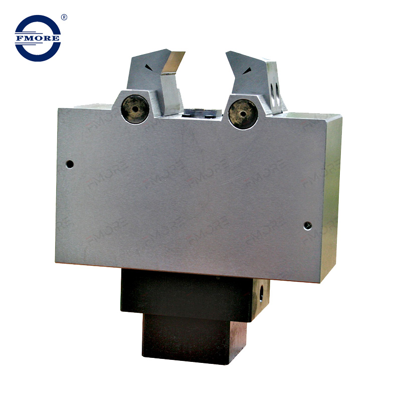
A traditional center support device mounts directly to the lathe bed ways. It features three adjustable arms. These arms are typically equipped with bronze tips or roller bearings. They contact the workpiece at 120-degree intervals. This stationary, rigid radial support captures the shaft at a specific point. It acts as an intermediate anchor that absorbs cutting vibrations. It prevents the material from bowing away from the tool. The base is cast iron or heavy steel, designed to dampen harmonics generated during heavy roughing cuts.
A follow rest mounts directly to the lathe carriage. It travels along the Z-axis with the cutting tool. It typically utilizes two contact points positioned opposite and above the cutting insert. Because it moves with the carriage, it provides constant, adjacent support directly at the shear zone. It prevents deflection exactly where the cutting pressure is applied. The follow rest is bolted to the saddle, meaning its alignment is relative to the toolpost rather than the machine bed.
Specifying the correct support mechanism depends entirely on the machining operation and the part geometry. You must evaluate the tool path, the required access to the part, and the volume of material being removed.
Stationary Bed Support: This is indispensable for end-face machining, deep-hole drilling, and internal boring on long parts. A tailstock live center cannot be used here because it blocks access to the part's face. It is the preferred choice for heavy roughing operations in the middle of a long shaft. It provides massive rigidity for high metal removal rates. You lock it down, indicate the part, and rough out the journals.
Carriage Mounted Support: This device is ideal for turning long, continuous outside diameters. The tool requires constant adjacent support. It prevents deflection directly at the shear zone across the entire length of the cut. It is perfect for threading long lead screws or turning slender shafts from end to end. You set the fingers just behind the cutting tool to ride on the freshly machined surface.
| Feature | Stationary Bed Support | Carriage Mounted Support |
|---|---|---|
| Mounting Location | Lathe Bed Ways | Lathe Carriage / Saddle |
| Movement | Fixed in Z-axis | Travels with the cutting tool |
| Contact Points | Three (120 degrees apart) | Two (Opposite and above tool) |
| Best Application | End-facing, boring, heavy roughing | Long continuous OD turning, threading |
| Primary Limitation | Tool cannot pass through the support area | Cannot support heavy plunge cuts or boring |
Traditional manual systems require an operator to physically adjust bronze or roller-tipped fingers using threaded knobs. This process demands high skill, patience, and a dial indicator to ensure the shaft is perfectly centered. The operator must feel the tension on the rollers to avoid pushing the part off-center. Conversely, a modern CNC Steady Rest utilizes programmable actuation to open and close the arms automatically. These systems feature internal geometries that move all three arms simultaneously. This ensures self-centering precision without manual intervention. The internal cam mechanisms guarantee that the clamping center remains consistent, regardless of slight variations in the raw stock diameter.
Automated systems rely on either hydraulic or pneumatic actuation. Hydraulic systems integrate directly with the machine tool's hydraulic unit. They deliver immense, consistent clamping force suitable for heavy-duty roughing on tough alloys. You can adjust the hydraulic pressure via a proportional valve to suit the material. Pneumatic systems offer lighter clamping pressures. They are ideal for thin-walled tubes or delicate materials where hydraulic pressure might crush or distort the workpiece. Selecting the right actuation method ensures clamping force consistency across varying material types. A crushed tube is just as useless as a deflected shaft.
Integrating an automated support system requires interfacing with the machine tool controller via specific M-codes. This allows the part program to command the arms to open, close, or adjust pressure dynamically during the cycle. For high-volume turning cells, the scalability benefits are massive. Automatic self-centering capabilities eliminate manual setup time between parts. Programmable positioning along the Z-axis allows the support to move out of the way for specific tool paths. You can program a tow-along feature where the carriage drags the support base to a new position, locks it down, and continues machining. This drastically reduces cycle times and operator intervention.
The workflow sequence for installation dictates the accuracy of the entire operation. You must mount and rough-position the support base on the lathe bed before finalizing the alignment and indicating sequence at the chuck. Securing the base to the ways first ensures that the frame is rigid and square to the spindle axis. Clean the ways thoroughly. Any chip trapped under the base will tilt the frame and induce a taper. Only after the base is locked down should you bring the workpiece into the work envelope.
Centering a long shaft is a highly technical process. You cannot simply clamp the arms onto raw, unmachined stock and expect accuracy. Raw bar stock is rarely perfectly round or straight. The machinist must first turn a clean, concentric journal on the shaft. If turning a journal is impossible due to the part's length or shape, you must utilize a cathead adapter. You must indicate the shaft at the chuck to ensure zero runout before setting the support fingers against the newly machined journal. If the chuck end is running out, the support end will fight it, causing the part to flex twice per revolution.
Aligning the shaft to the true spindle centerline requires a precise machinist workflow known as the "tap in" method. You cannot rush this process.
Set a dial indicator on the shaft near the chuck. Zero the dial to establish the true centerline reference. This confirms the chuck jaws are holding the part true.
Move the indicator down the shaft to the support location. Rotate the spindle by hand to find the lowest point (bottom dead center) of the shaft's sag. Note the total indicator reading.
Bring the bottom two rollers up to contact the shaft lightly. Do not apply heavy pressure yet.
Use a soft dead-blow mallet to gently "tap in" the workpiece while adjusting the bottom roller tension sequentially. You must bring the indicator back to zero.
Bring the top roller down to lock the shaft in place. Verify the indicator still reads zero. You are aligning the shaft to the true spindle centerline without pushing the workpiece off-axis or inducing an upward bow.
Improper setup introduces severe risks to the workpiece and the machine tool. You must anticipate these failures before you press cycle start.
Risk: Roller walk and surface marring on finished diameters. Mitigation: Ensure proper roller material selection. Use non-marring synthetic rollers for finished surfaces. Apply generous flood coolant to flush chips away from the contact patch. Maintain equal tension adjustment across all three arms.
Risk: Clamping on out-of-round stock, which transfers runout into the machined profile. Mitigation: Always pre-machine a concentric band for the rollers to ride on. Utilize specialized workholding adapters like a spider or cathead for rough, irregular stock.
Risk: Thermal expansion causing the shaft to bind in the rollers. Mitigation: Monitor the part temperature during heavy roughing. Adjust the tailstock pressure and roller tension if the part grows significantly in length or diameter.
Eliminating taper and runout on high-value materials translates directly to the bottom line. When machining large stainless steel, titanium, or Inconel shafts, a single scrapped part due to deflection can cost thousands of dollars in material and lost spindle time. Proper center support guarantees tolerance adherence. It drastically reduces scrap rates and ensures dimensional stability across the entire batch. You stop fighting the machine and start producing predictable results. The cost of the support equipment is often recovered in the first production run of complex shafts.
Vibration is the enemy of carbide cutting tools. When a long shaft chatters, the microscopic impacts shatter the cutting edge of the insert. By eliminating chatter and stabilizing the shear zone, rigid radial support prevents micro-chipping. This extends tool life significantly. It lowers consumable costs and reduces the frequency of machine stops for insert changes. You can run harder grades of carbide and push the surface footage higher because the cutting edge remains engaged in a stable cut rather than bouncing off the workpiece.
There is a balance between the upfront setup time required to indicate a manual system and the operational efficiency gained during the cut. Dialing in the rollers takes time. However, it unlocks the ability to run higher surface speeds, heavier depths of cut, and faster feed rates. The time saved by aggressive machining without part deflection heavily outweighs the initial setup investment. In a production environment, automating this process with programmable arms removes the setup penalty entirely, yielding massive throughput gains.
Evaluate your current lathe bed design and way configuration to determine mounting compatibility for a center support system.
Calculate the L:D ratios of your most problematic parts to identify exactly where deflection is destroying your margins and causing scrap.
Consult with workholding engineers to specify the correct clamping range, roller materials, and actuation type for your specific turning applications.
Implement a standardized setup procedure for your machinists, mandating the use of a dial indicator and the "tap in" method for all long shaft operations.
A: It is required when turning shafts with a Length-to-Diameter (L:D) ratio exceeding 6:1. It is also mandatory for end-facing, deep-hole drilling, or internal boring on long parts where a tailstock live center cannot be used.
A: While a tailstock supports the very end of a shaft, it physically blocks access to the end-face. Operations like boring, drilling, or facing require the end of the part to be open, making intermediate radial support necessary.
A: You must first turn a concentric band on the workpiece. Indicate the shaft at the chuck to establish zero runout, then adjust the three support fingers against the machined band until the shaft is aligned with the spindle centerline.
A: You must install and position the base on the lathe bed first. Next, indicate the chuck-side of the shaft. Finally, move the indicator to the support zone and adjust the rollers to match that established centerline.
A: A steady rest mounts stationary to the lathe bed, providing support at a fixed location. A follow rest mounts to the carriage and travels with the cutting tool, providing continuous support directly at the cut.
A: Yes, but not directly. You must use a cathead or spider adapter. This device clamps onto the irregular stock and provides a perfectly round, concentric outer bearing surface for the rollers to ride against.
A: Marks are typically caused by excessive clamping pressure, incorrect roller material for the finish requirements, or metal chips getting trapped between the rollers and the workpiece. Proper coolant flow and tension adjustment prevent this.

