
- All
- Product Name
- Product Keyword
- Product Model
- Product Summary
- Product Description
- Multi Field Search


Views: 0 Author: Site Editor Publish Time: 2026-08-13 Origin: Site


Machining long, slender shafts or heavy cylindrical components introduces unavoidable physical challenges on the shop floor. Operators constantly battle radial deflection, chatter, and harmonic vibration when turning extended parts. Relying solely on a chuck and tailstock for parts with a high length-to-diameter (L:D) ratio leads to compromised dimensional tolerances, accelerated tool wear, and unacceptable scrap rates. Selecting the wrong workholding support introduces severe collision risks and cycle-time bottlenecks that cripple production schedules.
Mitigating deflection requires integrating the correct workholding system directly into the machining process. This guide evaluates the primary types of support mechanisms available for turning centers, comparing their actuation methods, automation capabilities, and integration requirements. Manufacturing engineers can use this technical evaluation to specify the right solution for their specific production environment. Proper selection ensures consistent part quality, protects spindle bearings, and maximizes material removal rates without sacrificing safety.
Automation Dictates Selection: High-volume CNC environments rely almost exclusively on hydraulic, self-centering steady rests, whereas manual rests are reserved for low-volume, highly custom, or legacy turning operations.
Integration Complexity: Retrofitting a CNC lathe steady rest requires evaluating existing machine clearances, programmable M-code availability, and hydraulic/pneumatic infrastructure.
Surface Finish Protection: Roller material selection and precise clamping pressure control are critical decision factors to prevent part marking on finished or semi-finished surfaces.
Programmability Drives Flexibility: Servo-driven steady rests offer the highest scalability for families of parts with varying diameters, eliminating manual intervention during changeovers.
Establishing the baseline length-to-diameter (L:D) ratio is the first step in process planning. Typically, any part exceeding a 3:1 or 4:1 ratio requires intermediate support. Without it, the cutting forces push the workpiece away from the tool insert. This radial deflection causes tapering along the shaft length, making it impossible to hold tight concentricity and cylindricity tolerances. Applying a Steady Rest at the optimal position counteracts these cutting forces. It physically holds the part on the rotational axis, ensuring the programmed tool path matches the actual machined geometry perfectly.
When setting up a long shaft, operators must measure runout before and after engaging the support arms. Dial indicators placed near the support point will confirm if the clamping force is pushing the part off-center. Proper alignment requires sweeping the support body with an indicator mounted to the turret, verifying it sits perfectly parallel to the Z-axis guide ways. Any angular misalignment will induce a bind as the part rotates, leading to premature roller failure and severe taper on the finished workpiece.
Long workpieces act like tuning forks during the turning process. As the insert engages the material, it generates harmonic vibrations that manifest as chatter marks on the machined surface. Chatter destroys surface finish requirements and chips carbide cutting inserts prematurely. Intermediate support fundamentally changes the natural frequency of the workpiece, dampening these harmful vibrations effectively. Machinists can then optimize speeds and feeds, increasing material removal rates significantly without sacrificing tool life or surface quality.
To maximize vibration control, operators often adjust the position of the support relative to the cutting tool. Placing the support too far from the cut allows the unsupported section to vibrate. In heavy roughing applications, moving the support closer to the active cutting zone provides maximum rigidity. Some setups utilize two supports on extremely long shafts, dividing the unsupported length into shorter, more rigid segments that resist harmonic resonance.
Heavy forgings and large castings place immense stress on machine tool components. Supporting the physical mass of a heavy workpiece is critical. Relying only on the main spindle and tailstock centers concentrates the entire load on the bearings. Over time, this leads to premature spindle bearing failure and tailstock distortion. A properly positioned support distributes this massive weight, acting as a load-bearing bridge. This protects the machine's internal kinematics while maintaining strict alignment during aggressive roughing passes.
When machining massive components like turbine shafts or marine propeller shafts, the weight alone can cause the part to sag in the middle. This sag, known as catenary deflection, throws off all diametrical measurements. Engaging the support arms lifts the center of the part back to the true centerline of the machine. Operators must carefully calculate the required lifting force to overcome the part's weight without over-compensating and bowing the shaft upward.
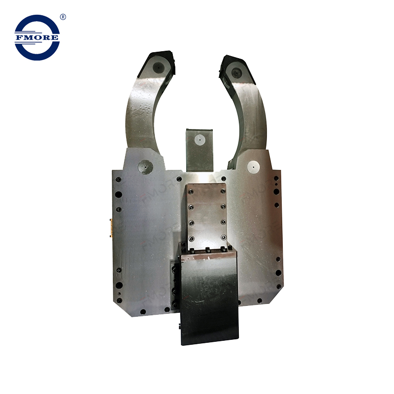
Manual configurations utilize independently adjusted quills, typically featuring three contact points. Operators must manually dial each quill to center the workpiece, requiring dial indicators, patience, and significant skill. The setup process involves bringing each quill into contact with the part while constantly checking runout. If one quill is too tight, it pushes the part off-center, requiring the operator to back it off and adjust the opposing quills.
The best use cases include tool rooms, repair shops, and low-volume production where setup time is less critical than upfront equipment cost. They excel in one-off repair jobs where part diameters vary wildly. However, they are entirely incompatible with automated loading and unloading systems. There is a high risk of operator error when establishing true center, and operators cannot adjust the clamping force dynamically during the machining cycle.
Hydraulic systems feature actuated arms that move simultaneously. This synchronized movement clamps the workpiece and ensures repeatable, automatic centering. Internal cam mechanisms or wedge designs drive the arms evenly toward the center line. This is the industry standard for a CNC Lathe Steady Rest in mid-to-high volume production environments, bridging the gap between rigid support and automated efficiency.
The advantages are substantial for cycle time reduction. They offer rapid clamping and unclamping capabilities, and the holding force remains highly consistent across thousands of cycles. They integrate seamlessly with CNC part programs via standard M-codes, allowing unmanned operation and robotic machine tending. Operators can adjust the hydraulic pressure at the pump to fine-tune the clamping force for different materials and wall thicknesses.
Pneumatic designs operate similarly to hydraulic models but use compressed air. They feature air-actuated self-centering arms, relying on shop air pressure rather than hydraulic fluid. These units are best suited for machining lighter materials like aluminum, composites, and plastics. They are also mandatory in clean-room environments or medical manufacturing where hydraulic fluid leaks are strictly unacceptable.
The primary limitation is the lower maximum clamping force. Air is compressible, unlike hydraulic fluid, making them unsuitable for heavy roughing on steel alloys. They are also highly susceptible to clamping pressure fluctuations if the shop air supply is inconsistent. Shops utilizing pneumatic systems must install dedicated air regulators and water traps to ensure consistent, clean air reaches the internal cylinders.
Servo-driven models represent the pinnacle of workholding automation. They feature fully programmable arms driven by precision servo motors. The CNC control treats the unit as an additional, fully interpolated machine axis. High-mix, high-volume environments benefit the most, as they are ideal for machining stepped shafts or families of parts with varying diameters.
The system allows for dynamic clamping pressure adjustments mid-cycle and enables automatic diameter changes without any manual setup or intervention. This provides the absolute highest level of process automation available for shaft turning. Programmers can command the arms to open slightly to clear a shoulder, then close again on a smaller diameter, all while the spindle continues to rotate.
Grinding operations require a different approach. Shoe-type rests use ultra-precise, low-friction sliding shoes instead of rolling elements. These shoes are typically made from carbide, PCD, or bronze. Operators adjust them via micrometer-level hydraulic or manual controls. They are exclusively used on CNC cylindrical grinding machines handling extremely tight tolerances.
The main advantage is the elimination of roller-induced roundness errors. Rollers can sometimes transfer their own runout to the workpiece. Solid shoes provide continuous, vibration-absorbing dampening on highly finished surfaces without leaving track marks. Proper coolant application is critical with shoe-type rests to maintain a hydrodynamic lubrication film between the shoe and the rotating workpiece.
| Steady Rest Type | Actuation Method | Best Application | Automation Level |
|---|---|---|---|
| Manual | Hand-cranked quills | Tool rooms, one-offs | None |
| Hydraulic | Fluid pressure | High-volume production | High (M-code) |
| Pneumatic | Compressed air | Clean rooms, plastics | High (M-code) |
| Servo-Driven | Electric servo motor | High-mix, stepped shafts | Maximum (Full Axis) |
| Shoe-Type | Micro-hydraulic/Manual | Precision grinding | Medium |
Evaluating the diameter range is a critical first step. You must compare the minimum and maximum clamping capacity of the arms against your shop's typical part mix. Selecting a unit with too narrow a range limits future job flexibility. Conversely, oversized units may cause tool clearance issues on smaller parts. Load bearing capacity is equally vital. You must match the rated weight capacity to the heaviest forgings or castings being machined. Exceeding this limit causes internal component failure.
Evaluate stepped profiles to determine if the arms need to open wide enough to clear large shoulders or flanges during longitudinal travel along the bedways. If a part has a large flange in the middle, the support arms must open completely to allow the carriage to pass, or the setup must utilize two separate supports on either side of the flange.
Interference modeling prevents catastrophic machine crashes. You must assess the physical footprint of the body and mounting bracket, comparing this against turret tooling lengths, tailstock travel limits, and sheet metal enclosures. Mounting styles dictate operational flexibility. Fixed mounting involves bolting the bracket directly to the bedways, providing maximum rigidity during heavy-duty cutting but limiting longitudinal flexibility.
Traveling carriage mounting attaches the unit to the Z-axis carriage, allowing it to follow the tool path closely. Programmable towing involves dragging the unit along the bedways. The Z-axis carriage connects via a programmable coupling bracket, positioning the support exactly where needed before cutting begins. This requires careful macro programming to ensure the coupling pin engages and disengages correctly without binding.
Proper lubrication integration dictates the lifespan of the internal mechanisms. Choosing between manual grease points and automated systems is an important operational decision. Automated central lubrication systems connect directly to the CNC’s lube cycles, which is absolutely critical for continuous-duty rollers and internal pivot points. Lack of lubrication leads to seized rollers, which will immediately score the workpiece and destroy the bearings.
Ingress protection keeps the unit functioning. You must specify positive air-purge sealing systems that create an internal overpressure. This continuous air flow prevents fine swarf, cast iron dust, and highly pressurized coolant from entering the internal roller bearings and cam mechanisms. Operators should inspect the air purge lines weekly to ensure they are not pinched or disconnected.
Understanding features-to-outcomes ensures part quality. Proportional pressure control valves translate hydraulic pressure into secure holding force, preventing crushing thin-walled tubing or distorting hollow shafts. Roller selection directly impacts the final surface finish. You must evaluate steel, carbide, or synthetic rollers carefully based on the application.
Steel rollers are durable for clamping on raw stock and rough forgings. Synthetic or composite rollers are mandatory when clamping on previously finished surfaces. They prevent galling and unwanted track marks on the final part geometry. When using synthetic rollers, operators must limit the maximum spindle RPM to prevent the rollers from melting due to excessive friction and heat generation.
Weighing the upfront cost against cycle time reduction requires careful analysis. The high capital expenditure of a servo-driven or hydraulic unit can be intimidating. However, you must compare this against the labor savings of automated centering. Faster machining feeds and reduced scrap rates often yield a rapid return on investment. Unmanned overnight running is impossible without reliable, automated workholding.
Maintenance overhead is a continuous operational reality. You must account for the ongoing maintenance of hydraulic lines and valves. Automatic lubrication systems require regular fluid top-offs and line inspections. The cost of replacement wear parts, specifically precision rollers and wiper seals, must be factored into the annual tooling budget. Ignoring maintenance leads to sluggish arm movement and inconsistent clamping pressure.
Engineers must balance flexibility versus rigidity. Highly adjustable, wide-range models offer excellent versatility for job shops but may sacrifice a degree of absolute rigidity. Narrow-range, heavy-duty models provide superior vibration dampening for dedicated, high-volume roughing lines. Selecting the right balance depends entirely on your specific production strategy and the types of materials you machine most frequently.
Inadequate hydraulic pressure poses a significant risk. If the machine's existing pump cannot supply sufficient flow, it leads to weak clamping. This causes the part to slip during heavy cuts, triggering system alarms or tool breakage. Mitigation requires conducting a thorough hydraulic audit prior to purchase. If the existing pump is undersized, installing standalone hydraulic power units (HPUs) is necessary. Adding proportional pressure valves allows operators to dial in the exact clamping force required for different materials.
Operators must also monitor hydraulic fluid temperature. Excessive heat thins the fluid, reducing the effective clamping force and causing the arms to drift during long cycles. Installing a heat exchanger on the HPU ensures the fluid remains at a stable operating temperature, guaranteeing consistent holding force from the first part of the shift to the last.
Catastrophic crashes represent the highest financial risk. Collisions between the cutting tool, turret, and support arms during rapid movements destroy equipment. Mechanical binding during carriage-towed repositioning can damage the bedways. Mitigation relies heavily on digital simulation. Utilizing CAM software with accurate 3D kinematic models is mandatory. Programmers must implement strict safety zones within the CNC control.
Import the exact 3D solid model of the support bracket and arms into the CAM software.
Define the open and closed states of the arms as distinct machine configurations.
Program safety clearance planes that force the turret to retract fully before moving past the support unit.
Utilize interlock switches and macro programming for M-code verification to ensure the arms are fully open or closed before spindle rotation begins.
Chips getting trapped between the rollers and the workpiece cause deep scoring. This ruins the surface finish and turns expensive material into scrap. Mitigation requires proactive chip management. Specifying units with integrated air purge and chip sweep systems is highly recommended. Additionally, utilizing programmable coolant flush nozzles directed precisely at the roller contact points washes away stringy chips before they can be pulled into the pinch zone.
Operators should program a brief dwell time after the arms open to allow the coolant flush to clear any remaining debris before the carriage moves to the next position. Regular inspection of the roller wipers is also critical; once the wipers wear down, they lose their ability to scrape fine chips off the rotating workpiece.
The choice of a support system dictates the upper limits of a CNC lathe's capability when machining long parts. While manual rests suffice for one-offs and repair work, automated production demands self-centering hydraulic or servo-driven systems. Proper selection eliminates deflection, dampens vibration, and protects machine tool bearings.
Audit your current machine's M-code availability and hydraulic pump capacity to determine integration feasibility.
Measure your bedway clearances and turret interference zones accurately to select the correct mounting bracket style.
Consult with a specialized workholding engineer to request a 3D interference model before finalizing procurement.
Establish a preventative maintenance schedule for roller replacement and hydraulic line inspection to ensure long-term reliability.
A: A steady rest mounts to the machine bed and remains stationary, supporting the workpiece at a fixed point. A follow rest mounts directly to the lathe carriage. It travels alongside the cutting tool, providing continuous support exactly where the cutting forces are applied.
A: Programming typically involves standard M-codes provided by the machine tool builder. For example, M10 might command the arms to close, while M11 commands them to open. Servo-driven models are programmed as an independent CNC axis using standard G-code coordinates.
A: Yes, retrofitting is common. It requires a custom mounting bracket designed for your specific bedway geometry. You also need available M-codes in the control, spare hydraulic or pneumatic lines, and sufficient physical clearance for the unit and turret.
A: Prevent marking by using synthetic or composite rollers instead of hardened steel. Ensure the clamping pressure is precisely controlled via proportional valves. Additionally, use directed coolant flow and air wipers to clear metal chips away from the roller contact points.
A: As a general machining rule, any workpiece exceeding a 3:1 or 4:1 length-to-diameter ratio requires intermediate support. Beyond this ratio, cutting forces cause unacceptable radial deflection, leading to chatter, poor surface finish, and dimensional tapering.
A: Replacement frequency depends entirely on the operating environment and clamping cycles. In heavy-production environments running cast iron, rollers may need replacement every six months. Regular inspection for flat spots, bearing play, and smooth rotation should be part of monthly preventative maintenance.

