
- All
- Product Name
- Product Keyword
- Product Model
- Product Summary
- Product Description
- Multi Field Search


Views: 0 Author: Site Editor Publish Time: 2026-09-09 Origin: Site


Standard 3-axis milling hits an operational bottleneck quickly. Operators waste valuable time manually flipping parts to machine multiple faces. Tolerance errors compound rapidly every time you unclamp and re-indicate a workpiece. These manual interventions destroy spindle uptime and erode margins on complex jobs.
Upgrading your machining center requires navigating complex technical specifications. Selecting an underpowered unit leads to severe chatter, scrapped parts, and frustrating integration failures. You must match the hardware precisely to your specific cutting forces and controller architecture. A mismatched system causes endless troubleshooting and downtime.
This guide provides a rigid technical evaluation framework for selecting a Horizontal Vertical Rotary Table. We focus heavily on rigidity, accuracy, controller compatibility, and physical envelope constraints. You will learn how to evaluate holding power, analyze drive mechanisms, and avoid costly setup mistakes on the shop floor.
Orientation Flexibility: A dual-purpose horizontal vertical rotary table allows shops to machine complex cylindrical parts (vertical mount) or large plates/fixtures (horizontal mount) without purchasing separate units.
Holding Power is Critical: Clamping torque often dictates the success of heavy milling operations; pneumatic brakes suit light work, while hydraulic systems are required for aggressive material removal.
Accuracy Metrics Matter: High-precision aerospace or medical parts require repeatability of ±2 arc-seconds or better, while standard job shop tasks can utilize more cost-effective ±15 arc-second models.
Integration Dictates Feasibility: Physical Z-axis clearance, motor type (stepper vs. servo), and electrical compatibility (4th axis pre-wiring) must be verified before procurement.
Adding a 4 axis rotary table transforms a standard mill into a multi-sided machining center. This hardware upgrade drastically reduces cycle times by eliminating the need for multiple custom workholding setups. Consider machining a complex hydraulic manifold block. On a standard 3-axis mill, you might need six separate operations to drill intersecting ports on all sides. With a rotary axis, you clamp the block once, machine the top, and then index the part to hit the remaining faces automatically.
You lower fixture costs significantly while increasing overall throughput. Shops justify this capital investment rapidly through increased spindle uptime and reduced operator intervention. Success depends on matching the equipment to your specific production runs. High-mix, low-volume shops benefit from rapid changeovers. High-volume production environments rely on continuous, uninterrupted machining cycles. Define your primary bottleneck before evaluating hardware specifications.
The table mounts flat directly onto the machine bed. It rotates around the Z-axis, creating a standard C-axis configuration. This setup provides massive structural support directly against the cast iron bed of the mill. Downward thrust loads transfer efficiently through the table bearings into the machine foundation, making it incredibly rigid.
Operators utilize this orientation for specific heavy-duty applications. Best use cases include large diameter bolt-hole circles, aggressive face milling, and supporting heavy fixture plates. A horizontal rotary table excels when you need to machine features on the top face of a large, flat component without losing rigidity. You can mount a large scroll chuck or a custom sub-plate directly to the faceplate to hold oversized castings that would otherwise require a massive boring mill.
The table mounts upright using a heavy-duty angle bracket. It rotates around the X or Y-axis, forming an A or B-axis configuration. This orientation exposes multiple sides of a workpiece to the spindle in a single clamping operation. It maximizes tool access and minimizes handling time.
This setup dominates complex part manufacturing. Best use cases include multi-sided machining using tombstones, continuous helical milling, and turning long cylindrical parts. Long parts require a tailstock for support to prevent deflection. A vertical rotary table allows you to machine three or four sides of a prismatic part seamlessly. When paired with a trunnion fixture, you can even hold multiple smaller parts on a single rotating beam, maximizing the number of parts produced per cycle.
The table rotates to a specific programmed angle and stops. Internal brakes clamp the faceplate rigidly in place. The machine then performs standard 3-axis drilling, tapping, or milling operations. The rotary axis remains completely stationary during the actual cutting process. The CNC program uses simple M-codes to unclamp, rotate, and re-clamp the unit.
This method demands specific hardware capabilities. High clamping torque is absolutely essential to resist cutting forces. Standard worm gear drives handle this work perfectly. You can utilize cost-effective stepper motors or basic servos because the motor does not need to synchronize movements during the cut. Positional indexing handles 90% of standard job shop requirements, from drilling radial holes in a flange to milling flats on a shaft.
The rotary axis moves in perfect tandem with the X, Y, and Z axes. The tool cuts material while the workpiece continuously rotates. This process generates complex 3D contours, impellers, feed screws, and custom cam profiles. It requires advanced CAM software to generate the toolpaths and a high-speed processor in the CNC control to handle the data execution.
Hardware requirements increase drastically for simultaneous operations. Zero-backlash mechanisms become mandatory to prevent gouging the part upon direction reversal. You need high-speed closed-loop servo integration. The motor must provide continuous dynamic torque to maintain smooth rotation against variable cutting pressures. If the rotary table lacks rigidity during simultaneous movement, the cutting tool will chatter, leaving a poor surface finish and destroying tool life.
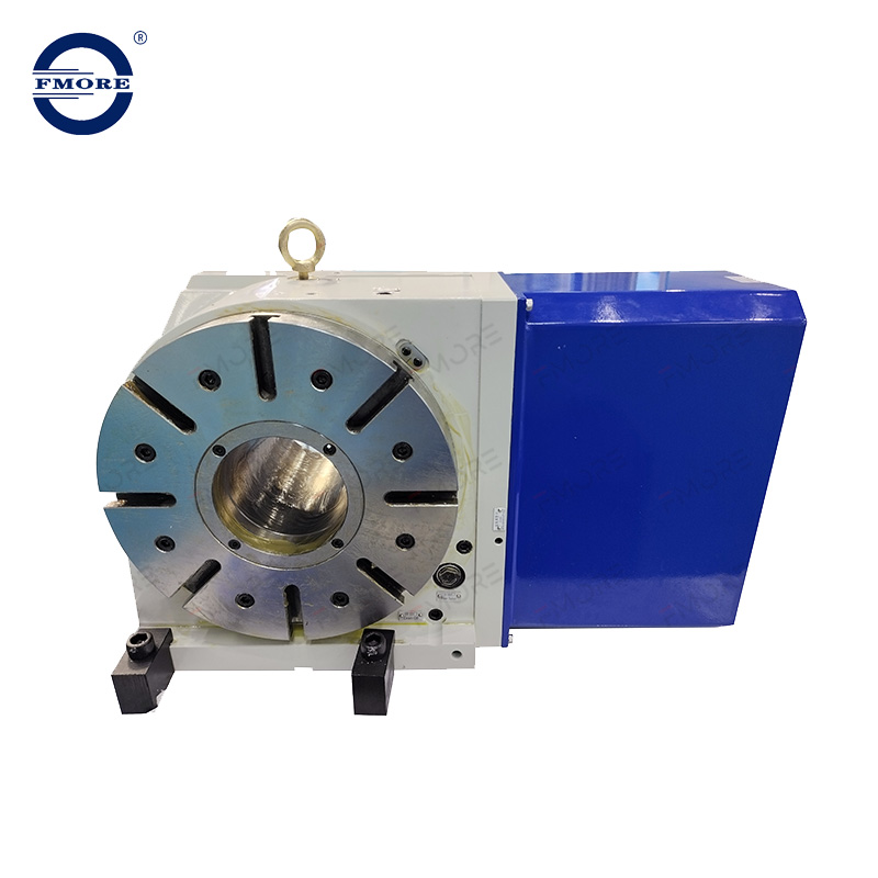
You must understand the critical difference between driving torque and clamping torque. Driving torque comes from the motor power. It dictates how fast the table can spin a heavy load and how well it pushes the part against the cutter during simultaneous machining. Clamping torque represents the holding power. It determines how much cutting force the table can withstand before slipping out of position during positional indexing.
Braking systems dictate your maximum metal removal rate. Machining far off-center generates massive leverage against the brake. If you drill a 1-inch hole 10 inches away from the center of rotation, the rotational force applied to the brake is immense.
| Braking System | Holding Power | Air/Fluid Requirement | Best Application |
|---|---|---|---|
| Pneumatic Brake | Low to Medium (approx. 200-500 Nm) | Standard shop air (80-100 PSI) | Aluminum components, light drilling, small diameter parts. |
| Hydraulic Brake | Very High (approx. 1000-3000+ Nm) | Dedicated hydraulic pump (500+ PSI) | Heavy steel roughing, large off-center drilling, titanium milling. |
Accuracy defines the table's ability to hit the exact programmed target angle. Repeatability measures its ability to hit that exact same angle consistently across hundreds of cycles. A table might have poor absolute accuracy but excellent repeatability. You can map out known accuracy errors in the CNC control using pitch error compensation, but poor repeatability ruins parts permanently because the error is random.
Establish strict industry baselines to prevent overspending on unnecessary precision. Standard job shop tasks generally require ±15 arc-second models. High-precision aerospace or medical parts demand repeatability of ±2 to ±5 arc-seconds. One arc-second equals 1/3600th of a degree. To put this in perspective, at the edge of a 10-inch diameter plate, a 15 arc-second error creates a physical deviation of roughly 0.0007 inches. Match the specification directly to your tightest blueprint tolerance.
The internal drive mechanism dictates the longevity, speed, and precision of the unit. Each system carries distinct advantages and operational trade-offs. Backlash—the slight play between gears when reversing direction—is the primary enemy of rotary precision.
| Drive Mechanism | Primary Advantage | Primary Disadvantage | Best Application |
|---|---|---|---|
| Worm Gear | Highly cost-effective, excellent natural holding torque. | Requires periodic backlash adjustment as bronze gears wear. | Heavy positional indexing, standard job shop milling. |
| Roller Cam | Zero backlash, higher RPM capabilities, low maintenance. | Higher initial purchase cost compared to worm gears. | Simultaneous 4-axis profiling, high-volume production. |
| Direct Drive | Maximum speed and extreme precision, zero mechanical wear. | Lowest dynamic torque, commands premium pricing. | High-speed light machining, ultra-precision grinding. |
Mounting a vertical rotary table raises the centerline of your part significantly. This physical footprint reduction severely limits your available Z-axis travel. Operators often discover too late that their longest drill bit cannot clear the top of the workpiece. You must measure the machine envelope carefully before purchasing.
Use this strict calculation framework for verifying tool clearance:
Identify your machine's maximum Z-axis daylight (distance from the spindle nose to the bare table).
Measure the centerline height of the proposed rotary table.
Add the maximum radius of your largest workpiece.
Add the thickness of any chucks, adapter plates, or fixture bases.
Subtract the total of steps 2, 3, and 4 from your maximum Z-axis daylight.
Compare the remaining number against your longest tool holder and cutting tool combination. If the tool is longer than the remaining space, you will crash the machine during tool changes.
Weight distribution limits vary wildly between horizontal and vertical mounting orientations. Horizontal mounting supports massive direct loads pushing straight down into the bearings. Vertical mounting creates a cantilevered load. The weight of the part pulls down, stressing the internal radial bearings and the worm gear. High-quality units utilize cross-roller bearings to handle these intense radial and axial loads simultaneously.
Long workpieces require immediate additional support. You must install a manual, pneumatic, or hydraulic tailstock. Unsupported long parts act like a tuning fork during machining. They chatter violently, destroy cutting tools, and eventually cause catastrophic bearing failure inside the rotary unit. Always calculate the length-to-diameter ratio of your parts. If the part extends more than three times its diameter past the faceplate, a tailstock is mandatory.
Motor selection dictates the entire electrical integration process. Stepper motors are budget-friendly and operate on an open-loop system. They work perfectly for basic, slow-speed indexing. Servo motors provide closed-loop feedback to the controller. They are strictly required for any simultaneous machining operations where positional tracking is critical.
Mismatched servo motors and drives cause expensive integration nightmares. A Fanuc-controlled mill typically requires specific Fanuc motors installed on the machining center rotary table. If you buy a table with a Mitsubishi motor for a Fanuc machine, the amplifiers will not communicate. You will spend thousands on replacement motors, custom cables, and specialized parameter tuning.
Evaluate your machine's current wiring status. "4th axis ready" machines contain the necessary internal wiring, servo amplifiers, and software options. They offer true plug-and-play capability. Retrofitting older machines requires purchasing external indexer boxes. These standalone boxes trigger via simple M-codes from the main CNC program. The machine sends a signal to the box, the box rotates the table, and then sends a completion signal back to the machine. This works for indexing, but external boxes cannot perform simultaneous interpolation.
Choose a CNC rotary table when your shop handles high production volumes. It handles heavy milling cuts effortlessly. It integrates directly into the CNC controller for seamless automated cycles. You need this hardware when your blueprints demand simultaneous multi-axis interpolation to generate complex sweeping geometries. The rigidity of a dedicated CNC unit far surpasses manual alternatives, allowing you to push modern carbide tooling to its limits.
Manual or semi-automated indexing tasks do not require full CNC integration. A dividing head excels at simple gear cutting, splines, or basic polygonal machining in repair shops or tool rooms. Use these tools when continuous rotation under heavy cutting load is not required.
Hybrid models offer excellent transitional value. They allow manual handwheel operation for simple prototype work. You can remove the handwheel and bolt on a servo motor later to upgrade the unit to full CNC integration as your production needs scale up. This provides flexibility for growing shops that cannot justify a full CNC unit immediately.
Parts requiring machining on compound angles demand a tilting rotary table (trunnion). This hardware provides both rotation (C-axis) and tilt (A or B-axis), enabling 3+2 positional or full 5-axis machining. It allows you to reach undercuts and machine complex aerospace brackets in a single setup.
You must weigh the severe trade-offs. Tilting tables introduce higher mechanical complexity. They suffer from reduced rigidity compared to a standard horizontal vertical rotary table because the cutting forces are suspended on a pivoting trunnion. They also require vastly more complex CAM programming, specialized post-processors, and advanced machine simulation software to avoid catastrophic spindle crashes.
You must tram the rotary table perfectly parallel to the machine's X-axis or Y-axis. This alignment is critical for off-center drilling on a vertical spindle. If the table sits slightly skewed, your drilled holes will drift off-location as the part rotates. Poor tramming causes tapered cuts, binding tailstocks, and severe geometric errors across the entire workpiece.
Follow this standard procedure for tramming a vertical setup:
Clean the machine table and the bottom of the rotary table thoroughly with a stoning block to remove burrs.
Mount the rotary table loosely to the T-slots.
Place a high-precision dial indicator in the machine spindle.
Sweep the indicator across the precision ground faceplate of the rotary table while moving the Y-axis (or X-axis, depending on orientation).
Tap the base of the table gently with a dead-blow hammer until the indicator reads zero runout across the entire travel distance.
Torque the mounting bolts evenly and sweep the faceplate one final time to verify it did not shift.
Shop environments destroy unprotected electronics rapidly. You must verify the IP ratings for coolant and chip ingress. High-pressure coolant systems easily blast past cheap rubber seals. Once synthetic coolant enters the motor housing, it shorts out the encoder and destroys the servo instantly. Look for units with positive air purge systems that maintain slight internal pressure to keep coolant out.
Outline strict maintenance realities for your operators. Worm gear systems require regular oil changes to flush out microscopic bronze particulates. You must check pneumatic or hydraulic brake pressure weekly to ensure maximum holding torque. Verify all cable management routing carefully. Loose cables snag on enclosures or way covers during rapid machine travel, ripping wires directly out of the motor connectors and causing immediate downtime.
A horizontal vertical rotary table delivers exceptional returns only if you match its specifications to your shop's reality. Its rigidity, accuracy, and physical dimensions must align perfectly with your specific machining center and part applications. Prioritize clamping torque for heavy indexing tasks. Choose zero-backlash drives for continuous 4-axis profiling. Match precision metrics to actual blueprint requirements to avoid wasting capital on unnecessary accuracy.
Take these concrete steps before finalizing any purchase:
Audit your machine's available Z-axis clearance physically using your longest tool and tallest fixture setup.
Verify controller compatibility, including specific amplifier and motor requirements, directly with your machine tool builder.
Calculate your required clamping torque based on the maximum distance off-center you plan to perform heavy roughing cuts.
Request physical test cuts from the table manufacturer if your parts require critical arc-second tolerances.
A: A horizontal rotary table mounts flat on the machine bed, rotating around the Z-axis for face milling and large bolt circles. A vertical rotary table mounts upright, rotating around the X or Y-axis to expose multiple sides of a part or support long cylinders with a tailstock.
A: Clamping torque requirements depend on your cutting forces and part radius. Light aluminum indexing requires minimal torque, often handled by pneumatic brakes. Heavy steel milling off-center demands high clamping torque provided by rigid hydraulic braking systems to prevent table rotation during the cut.
A: Most 3-axis mills can accept a 4th axis, but integration methods vary. "4th axis ready" machines have the necessary wiring and servo drives installed. Older or basic mills require an external indexer box that communicates with the machine controller via basic M-codes.
A: Choose a stepper motor for budget-friendly, simple positional indexing where speed is not critical. Choose a closed-loop servo motor if you need rapid positioning, high torque, or simultaneous 4-axis machining where the rotary axis moves in tandem with X, Y, and Z axes.
A: A machining center rotary table is built for heavy milling loads, continuous CNC interpolation, and automated production. A dividing head is typically used for manual or semi-automated positional indexing, gear cutting, and lighter tasks that do not require continuous rotation under heavy cutting pressure.
A: Mount a dial indicator in the machine spindle. Sweep the indicator across the precision ground faceplate of the rotary table while moving the X-axis. Tap the base of the table gently until the indicator reads zero runout across the entire travel distance, then lock the mounting bolts.
A: An arc-second is 1/3600th of a degree. Repeatability measures the table's ability to return to the exact same rotational position repeatedly. A rating of ±2 arc-seconds means the table will consistently hit its target angle with virtually zero deviation, which is critical for high-precision aerospace or medical components.

