
- All
- Product Name
- Product Keyword
- Product Model
- Product Summary
- Product Description
- Multi Field Search


Views: 0 Author: Site Editor Publish Time: 2026-08-10 Origin: Site


Machining long shafts introduces a fundamental physics problem on the shop floor. When radial cutting forces exceed the natural rigidity of the workpiece, the material bends. This physical limitation in unsupported turning operations dictates the boundary between a successful pass and a scrapped part. As the cutting insert engages the material, it generates lateral pressure. If the workpiece lacks sufficient structural resistance, it deflects away from the tool.
This deflection creates compounding costs in manufacturing. You immediately face dimensional inaccuracies, often manifesting as unwanted tapers across the length of the shaft. Severe chatter develops, destroying surface finishes and rapidly degrading cutting edges. On long or slender parts, these dynamics lead to unacceptably high scrap rates. The primary mechanical intervention to neutralize these radial cutting forces is the Steady Rest. By anchoring the workpiece mid-span, you shift the focus from inherent machine limitations to proper workholding strategy and setup evaluation.
Deflection Mitigation: A steady rest provides critical three-point radial support, counteracting tool pressure and preventing part flex in workpieces with high Length-to-Diameter (L/D) ratios.
Dynamic Rigidization: As turning progresses and the workpiece becomes thinner, its natural rigidity decreases; a steady rest counteracts this dynamic loss of structural integrity.
Vibration and Chatter Control: By anchoring the workpiece mid-span, steady rests dampen harmful harmonics, directly improving surface finish and extending tool life.
Manual vs. Automated Scalability: While manual steady rests offer cost-effective versatility for job shops, an automatic steady rest is engineered for high-volume CNC environments requiring programmable repeatability.
Implementation Risks: Improper setup or finger material selection can cause surface marring; successful deployment requires precise alignment, debris management, and specialized protection techniques.
The stability of a turning operation relies heavily on the Length-to-Diameter (L/D) ratio of the workpiece. When a part extends beyond a 3:1 ratio, it begins to lose rigidity. By the time the ratio reaches 6:1, unsupported turning becomes mathematically unstable for most materials. At these extended lengths, the radial tool pressure physically pushes the workpiece away from the cutting insert. The machine continues to feed the tool along the programmed path, but the material flexes outward. This mismatch between the programmed toolpath and the actual material position results in tapered parts that are oversized in the middle of the cut.
This instability worsens as the machining cycle progresses due to dynamic L/D degradation. Turning down the outer diameter (OD) progressively reduces the cross-sectional area of the workpiece. This reduction directly lowers the material's moment of inertia. As you remove material, the shaft becomes exponentially more prone to deflection. A part that was rigid enough for a roughing pass may lack the structural integrity required for a finishing pass. Operators must constantly monitor the changing dynamics of the workpiece.
| L/D Ratio | Machining Condition | Required Action |
|---|---|---|
| Under 3:1 | Highly Stable | Standard chucking, no additional support needed. |
| 3:1 to 6:1 | Marginal Stability | Tailstock support required. Monitor for chatter. |
| 6:1 to 10:1 | Unstable | Mid-span radial support mandatory to prevent deflection. |
| Over 10:1 | Highly Unstable | Multiple support points or specialized follow rests required. |
Unsupported mass creates resonant frequencies during machining. When the cutting tool engages a flexible workpiece, it induces vibrations. These vibrations bounce back and forth along the length of the shaft, creating a harmonic resonance known as chatter. Chatter leaves distinct, repeating diagonal marks on the surface finish and destroys dimensional accuracy. You can hear chatter before you see it; the high-pitched squeal is a clear indicator of process failure.
The effect of chatter cascades rapidly. Initial micro-vibrations hammer the cutting edge of the insert against the workpiece. This repeated impact chips or dulls the cutting edge. A degraded insert requires more force to shear the material, which in turn increases the radial cutting pressure. Higher cutting pressure forces the workpiece to deflect further, amplifying the vibration. Breaking this destructive cycle requires mechanical intervention to secure the unsupported mass.
Identify the source of the vibration by checking the tool overhang and insert condition.
Measure the workpiece to confirm the current L/D ratio.
Adjust feeds and speeds to disrupt the harmonic frequency.
If vibration persists, install mechanical support to anchor the part.
A steady rest captures the workpiece using a specific geometric arrangement. It utilizes three equidistant contact points, positioned 120 degrees apart around the circumference of the shaft. Two lower points support the weight of the part and resist downward cutting forces, while the top point locks the material in place and resists upward forces. This localized rigidity prevents the part from climbing the tool or deflecting away from it.
By establishing this rigid mid-span anchor, you can run aggressive depth-of-cut (DOC) parameters and higher feed rates. Without this three-point support, those same machining parameters would bend the shaft permanently or launch the part out of the chuck. The support acts as a secondary spindle bearing, effectively cutting the unsupported length of the shaft in half.
The heavy cast iron or steel frame of the steady rest, combined with its rollers or bronze fingers, acts as a mass dampener. It absorbs the harmonic frequencies generated at the cutting zone before they can travel down the length of the shaft. This dampening effect is critical for achieving superior surface finishes. You eliminate the chatter marks that cause parts to fail quality inspections.
Stabilizing the workpiece directly correlates with the ability to hold tight geometric dimensioning and tolerancing (GD&T) requirements. When the part cannot flex or vibrate, the cutting tool produces true cylinders. You gain strict control over cylindricity and runout, ensuring the final shaft meets precise engineering specifications. This control is especially important when machining bearing journals or seal surfaces.
Machinists rely on two distinct types of support mechanisms depending on the operation. A steady rest provides stationary support. It clamps directly to the lathe bed pathways and remains fixed in one axial location. You use it to support the end of a long shaft for facing and drilling operations, or to anchor the middle of a shaft while turning the OD on either side.
A follow rest provides dynamic, traveling support. It bolts directly to the lathe carriage and moves alongside the cutting tool. The support fingers sit exactly opposite the cutting insert, continuously counteracting radial thrust at the exact point of cut. You deploy a follow rest when turning long, extremely slender threads or continuous OD profiles where stationary support would interfere with the toolpath.
| Feature | Steady Rest | Follow Rest |
|---|---|---|
| Mounting Location | Fixed to the lathe bed. | Bolted to the moving carriage. |
| Support Type | Stationary, mid-span or end support. | Dynamic, travels with the cutting tool. |
| Primary Application | Heavy roughing, facing long shafts, internal boring. | Turning long slender profiles, threading long shafts. |
| Interference Risk | Can block toolpaths if turning the entire length. | Minimal, as it moves with the tool. |
Traditional manual systems consist of fixed, hinged frames equipped with individually adjustable fingers. These fingers typically feature bronze tips, brass pads, or roller bearings. The operator manually turns threaded dials to advance each finger until it contacts the workpiece. This process requires a dial indicator and a skilled touch to ensure the part remains perfectly centered.
These units are the best fit for low-volume production, repair shops, and custom manual lathe operations. They offer high versatility for handling odd-shaped or severely damaged parts. However, they come with significant trade-offs. Setup time is high. Achieving perfect centerline alignment relies heavily on operator skill and feel. Furthermore, if you are turning the diameter where the fingers rest, you must stop the machine and manually adjust the support as the part shrinks.
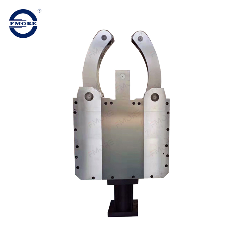
An Automatic Steady Rest utilizes hydraulically or pneumatically actuated arms. These arms are mechanically linked to close simultaneously, providing self-centering support around the workpiece. The operator controls the clamping action via foot pedals or programmed M-codes within the CNC program.
These systems are engineered for high-volume CNC turning centers, lights-out manufacturing, and automated cell integration. They eliminate the manual dialing-in process, ensuring rapid, repeatable clamping on every cycle. The trade-offs include a higher initial capital expenditure and complex machine integration involving hydraulic plumbing and ladder logic updates. Additionally, the fixed body of the unit consumes valuable space within the machine envelope.
Verify the machine has available hydraulic circuits and M-codes.
Mount the base bracket securely to the lathe bed or linear guideways.
Align the unit to the spindle centerline using a precision test bar.
Connect hydraulic lines and set the appropriate clamping pressure.
Test the open/close function via the CNC control before running a part.
Implementing workholding support requires calculating the break-even point for your specific production run. You must weigh the time lost to setup against the time gained through optimized machining parameters. Manually tramming a steady rest might take 30 minutes. If you are running a single custom shaft, that setup time is a necessary loss to prevent scrapping the part.
In production environments, the calculation shifts. The rigidity provided by the support allows for significantly increased material removal rates. You can double your feed rates and eliminate chatter-induced scrap. The time saved during the actual cutting cycle quickly offsets the initial setup time, driving overall profitability. You must analyze your batch sizes to determine the right approach.
A common failure point is the steady rest fingers gouging or scoring the workpiece during rotation. Hardened rollers can trap chips, embedding them into the finished surface. Bronze fingers can gall and transfer material onto the shaft, ruining the finish and requiring extensive polishing.
To mitigate these deflection and friction barriers, you must deploy physical protection tactics. Common methods include wrapping the bearing journal in heavy-duty electrical tape, applying sacrificial copper or brass shims, or using split-bushings. High-pressure boundary lubricants are also mandatory when using solid fingers to prevent friction welding.
For rough, non-concentric, or hot-rolled stock, direct roller contact is impossible. In these cases, you use the "cat head" or spider chuck technique. This involves sliding an external metal sleeve over the rough stock. You adjust set screws on the sleeve to dial it perfectly concentric to the spindle centerline. The steady rest rollers then ride on the smooth, concentric outer diameter of the cat head, completely protecting the rough workpiece inside.
Adding a large cast iron fixture to the bed of a lathe introduces severe clearance constraints. You must analyze the physical footprint of the unit before installation. It will consume Z-axis travel and limit how close the tailstock can approach the chuck. You must measure the available space carefully.
You must also evaluate potential interference with the machine turret and automated part catchers. Boring bars and long drills extending from the turret can easily crash into the frame. Programmers must model exact toolpaths and establish strict safe zones to avoid catastrophic collisions during rapid movements. A crash involving a heavy cast iron frame will cause severe damage to the machine tool.
A steady rest only functions correctly if it is perfectly aligned with the spindle centerline. You must tram the unit meticulously. If the fingers push the workpiece even a few thousandths of an inch off-center, you induce severe taper into the cut. The part will measure correctly at the support point but will be undersized or oversized at the ends.
Off-center clamping forces the shaft to flex during every rotation. This constant bending leads to rapid bearing wear, part distortion, and premature failure of the cutting insert. Use precision dial indicators to sweep the part and ensure the clamping forces are perfectly neutral relative to the spindle axis. Take the time to get this right before making chips.
The location of the steady rest places it directly in the path of flying chips and high-pressure coolant. This ingress of debris threatens the internal mechanisms. Chips can pack into the roller bearings, causing them to seize and drag across the workpiece. Coolant can wash away essential lubrication.
Establish strict baseline maintenance protocols. Operators must flush the roller bearings and hinge points daily. For hydraulic units, inspect the actuator seals for coolant contamination. Consistent lubrication of the internal wedges and arms is required to maintain clamping repeatability and prevent the self-centering mechanism from binding. Neglecting maintenance will lead to scrapped parts and expensive repairs.
Audit your current scrap rates and cycle times on shafts exceeding a 4:1 L/D ratio to identify immediate process improvement opportunities.
Evaluate your CNC lathe's existing hydraulic infrastructure and available M-codes to determine integration readiness for automated support systems.
Implement standard operating procedures for surface protection, utilizing cat heads or split bushings for rough stock to prevent marring.
Establish daily preventative maintenance schedules focusing on debris removal and roller bearing lubrication to ensure long-term repeatability.
A: You should deploy radial support when the workpiece length exceeds 3 to 6 times its diameter. The exact threshold depends on the material's natural rigidity, the aggressiveness of the cutting forces, and how much the diameter will be reduced during the turning operation.
A: A steady rest is fixed directly to the lathe bed and supports a specific axial location on the workpiece. A follow rest attaches to the carriage and moves alongside the cutting tool, providing continuous radial support directly opposite the tool thrust.
A: Prevent scoring by ensuring roller bearings are free of chips and spinning freely. Use high-pressure lubricants on solid fingers. For critical finishes, protect the surface using split bushings, copper shims, heavy tape, or by mounting a cat head over the shaft.
A: Yes, retrofitting is common. However, it requires evaluating the machine's existing hydraulic or pneumatic infrastructure, verifying available M-codes in the control, and designing custom mounting brackets to fit the specific bed geometry.
A: While the initial setup time increases, the actual machining cycle time usually decreases. The added rigidity eliminates chatter, allowing you to run significantly higher feed rates and deeper cuts than would be possible on an unsupported shaft.

